In modern power systems, the efficiency of transmission lines directly affects overall grid performance, operating costs, and reliability. Since transmission losses primarily occur due to conductor resistance and reactive power flow, engineers must carefully evaluate both design and operational strategies to minimize these losses. Below is a detailed technical review of methods to improve transmission line efficiency, from fundamental design choices to advanced system-level interventions.
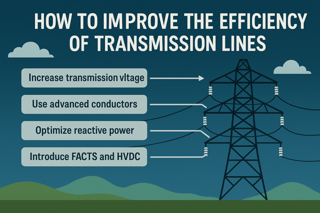
1. Raise Transmission Voltage
- Principle:
For a given power transfer (P), line current (I = \frac{P}{\sqrt{3} V \cos \phi}). Increasing line voltage (V) reduces current, thereby cutting (I^2R) losses. - Impact:
Doubling the voltage reduces losses by ~75%. - Application:
- Upgrading from 115 kV to 230 kV or from 230 kV to 380/400 kV (depending on system requirements).
- Requires redesign of insulation, tower clearances, and protection systems.
2. Conductor Optimization
- Reconductoring:
Replace ACSR with HTLS conductors (ACCC, ACSS, GAP conductors) to reduce resistance per km and increase ampacity without new towers. - Bundled Conductors:
Multiple sub-conductors per phase reduce effective reactance, mitigate corona effects, and improve current-carrying capability. - Design Considerations:
- Sag-tension balance
- Corona inception voltage
- Thermal rating under worst-case weather
3. Reactive Power and Voltage Control
- Shunt Compensation:
- Shunt capacitors, STATCOMs, or synchronous condensers improve power factor and stabilize voltage, reducing reactive current.
- Series Compensation:
- Series capacitors reduce line reactance, allowing higher power transfer at lower current.
- Transformer Tap Changers (OLTC):
Maintain optimal secondary voltage, minimizing overcurrent due to low-voltage operation.
Our most read Posts you may like are as follows
- Transmission Line Design Important Points
- Panels required inside substations
- Electrical MCQs with Explanation of Answers
- Transmission Lines design Basics
- Inside a 380kV BSP: Overall Layout Drawing Explained
- 380kV Gantries & Gantry Equipment
- Top Electrical Engineering Courses on Coursera
- Vector Group of Transformers
- Top Excel Functions Every Engineer Should Master
4. FACTS Devices
- Static Var Compensator (SVC): Controls reactive power dynamically.
- STATCOM: Voltage source converter-based control; faster response and smaller footprint.
- TCSC/SSSC: Controls series impedance, redistributes flows, and prevents overload of certain corridors.
- Impact: Enhances transfer capability, improves voltage stability, and indirectly reduces (I^2R) losses.
5. HVDC Transmission
- When to Use:
For very long distances (>600 km overhead, >50 km submarine) or large bulk transfers. - Advantages:
- No reactive power flow
- Lower line losses compared to AC
- Controllable power flow
- Hybrid Approach:
Integrating HVDC backbones with existing AC grid enhances stability and reduces congestion.
6. Dynamic Line Rating (DLR)
- Principle:
Conductor temperature is a function of ambient temperature, solar radiation, and wind cooling. Real-time monitoring allows dynamic capacity instead of conservative static ratings. - Implementation:
- Sag sensors, weather stations, and fiber-optic temperature sensors.
- Enables better utilization of transmission corridors without overloading.
7. System Operation and Dispatch
- Optimal Power Flow (OPF):
Advanced algorithms can minimize losses by redistributing loads across parallel circuits and optimizing generator dispatch. - Energy Storage Integration:
Locally placed storage reduces long-distance transfers during peak demand, lowering transmission stress. - Demand-Side Management:
Shifting load profiles helps reduce peak loading and associated line losses.
8. O&M and Reliability Measures
- Insulator Maintenance: Cleaning and replacing contaminated insulators prevents leakage currents and partial discharges.
- Thermal Imaging: Detects hot spots and overloaded joints.
- Vegetation Management: Prevents flashovers and ensures safe clearances.
- Condition Monitoring: On-line monitoring of sag, conductor temperature, and line impedance improves predictive maintenance.
Efficiency Gain Estimation Example
For a 200 km, 230 kV line transmitting 300 MW:
- Losses at 230 kV (using ACSR): ~7.5 MW
- After reconductoring with ACCC: losses drop to ~5 MW
- If voltage is upgraded to 400 kV: losses further drop to ~2.5 MW
This shows how combining conductor optimization and voltage upgrade drastically improves efficiency.
Conclusion
Improving transmission line efficiency is not a one-time task but a continuous engineering process involving design, operation, and maintenance.
- Short-term gains: Reactive power compensation, OLTC adjustments, insulator cleaning.
- Medium-term measures: Reconductoring, bundled conductors, installation of STATCOMs or series capacitors.
- Long-term strategies: Voltage upgrades, HVDC integration, and wide deployment of DLR systems.
In an expanding grid environment—especially with growing renewable penetration—these measures are essential to ensure reliable, efficient, and cost-effective power delivery.
380kV Substation Design, electrical, Electrical MCQs, Extra High Voltage EHV Substation Design, Interview Preparation, MCQs, NTS Past Papers, Past Papers