In today’s digital era, our daily lives depend heavily on the cloud. Financial transactions, communications, and business operations all rely on data centers. These facilities are the hidden engines of the modern world. However, they are now under intense scrutiny. Data centers frequently make headlines for their massive power consumption and their impact on the national grid, including coverage in The Irish Times on the morning of this presentation.
This article provides a detailed, professional breakdown of the electrical power system within a data center, tracing the journey of electricity from the transmission pylon right into the back of a server rack. We’ll demystify the components, explain the critical need for resilience, and explore how data centers might evolve from being perceived as part of the grid congestion problem to becoming part of the solution.
Part 1: The Scale of the Challenge
Power Density: A Different League
To understand data center engineering, one must first grasp the staggering scale of their power demand.
| Building Type | Typical Power Density (Watts/m²) |
|---|---|
| Church / Small Bank | ~15 W/m² |
| Hotel | ~25 W/m² |
| Modern Office (AC) | ~60 W/m² |
| Data Center (Low Density) | ~500 W/m² |
| Data Center (High Density) | Up to 2,000 W/m² |
Visualising the Load: A high-density data hall can draw 2 kilowatts per square meter. Imagine 20-30 standard 1kW electric heaters packed into a single server rack, and then picture thousands of these racks in one building. That’s the thermal and electrical challenge.
The Megawatt Reality:
A typical high-intensity data center with 10,000 m² of “white space” (the area containing servers) can have a load of 20 Megawatts (MW). For comparison, a large office building of the same floor area might use just 0.6 MW.
Grid Impact: In Ireland, data centers currently account for approximately 1 Gigawatt (GW) of the national demand, out of a peak grid load of around 5.5 GW. This massive, concentrated demand is why new, large data centers cannot simply connect to the local medium-voltage network; they require a direct connection to the high-voltage transmission grid at 110 kV or 220 kV.
Part 2: The High-Level Power Journey – An Overview
The schematic below outlines the complete power path. The building services engineer typically gets involved from the Medium Voltage (MV) switchgear downward, with the high-voltage connection being a specialist utility contract.
[Transmission Grid: 110/220 kV]
↓
[ESB-Owned HV Switchgear & Substation]
↓
[HV/MV Transformer (e.g., 220kV to 20kV)]
↓
MV Switchgear ← (Building Services Design Starts Here)
↓
[MV/LV Transformers (20kV to 400V)]
↓
[Main Low Voltage (LV) Switchboard] ← [Standby Generator]
↓
[Uninterruptible Power Supply (UPS)]
↓
[LV Distribution: Busbars, PDUs, RPPs]
↓
[Server Racks & IT Load]
Core Principle: Resilience through Duplication
From the MV stage onward, everything is duplicated in an ‘A’ and ‘B’ configuration. This ensures that if one complete power path fails, a second, independent path can take over seamlessly, guaranteeing “five-nines” (99.999%) uptime.
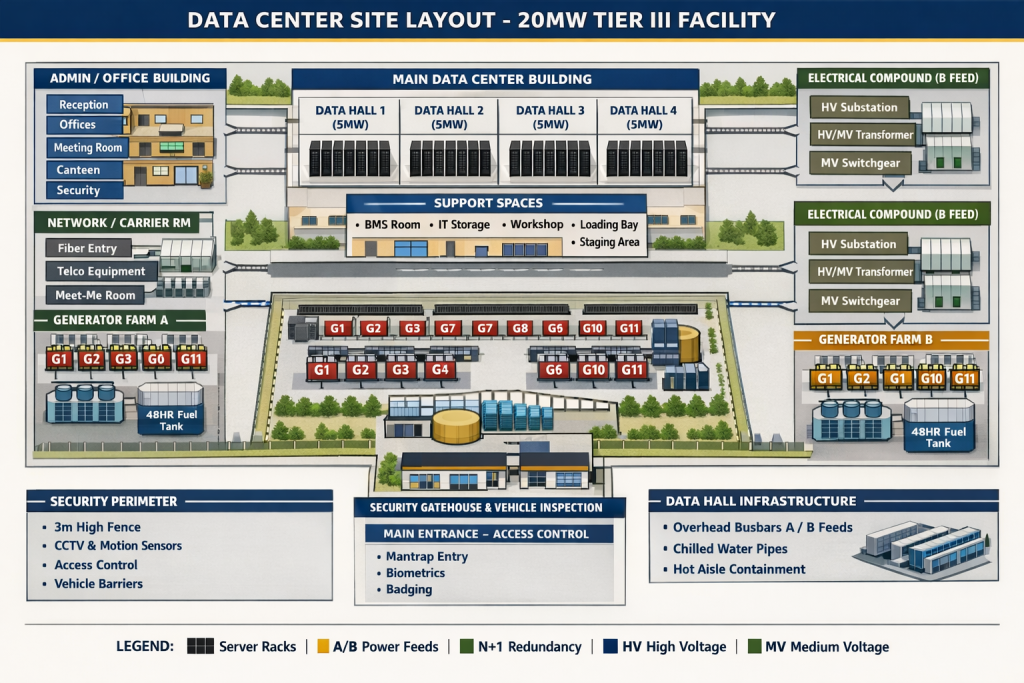
Fig. 1 A typical AI Generated DATA Center Layout
Part 3: Component Deep Dive
1. High Voltage (HV) Connection & Transformation
- Connection: Power is taken directly from transmission pylons. The data center developer typically funds and builds a dedicated substation, which is then handed over to EirGrid/ESB.
- HV Switchgear Types:
- Air Insulated Switchgear (AIS): Conductors are separated by air over distances of 1-2 meters. This is robust but requires a vast amount of space.
- Gas Insulated Switchgear (GIS): Conductors are enclosed in sealed compartments filled with SF6 gas. It is extremely compact (about 1/3 the size of AIS) but requires careful monitoring due to SF6’s high global warming potential.
- Transformers: Massive units (e.g., 50 MVA, 63 MVA) step down voltage from transmission levels (110/220 kV) to distribution levels (10/20 kV).
Below are our posts related to Substation Design
- 380kV Gantries & Gantry Equipment
- Inside a 380kV BSP: Overall Layout Drawing Explained
- 380kV Gas-Insulated Switchgear (GIS)
- Power Transformers
- Auxiliary Transformer Sizing for a 380kV BSP
- Vector Group of Transformers
2. Medium Voltage (MV) Distribution
MV (1,000V to 35,000V; in Ireland, 10kV or 20kV) is distributed around the site to various electrical plant rooms adjacent to each data hall.
3. Standby Diesel Generators: The Long-Term Backup
Generators are not just for emergencies; they are now central to grid stability discussions (“Demand Side Management”).
- Function: They provide long-term backup power (typically 48+ hours) if the grid fails.
- Components: A large industrial diesel engine (e.g., a V12 configuration) coupled to an alternator, with a large radiator for cooling.
- Key Design Considerations:
- Fuel Storage: Modern designs use integral “belly tanks” beneath each generator container, holding ~48 hours of fuel, rather than a risky centralised tank farm.
- Fuel Polishing: Essential systems to remove water condensation and microbial growth (“sludge”) from diesel, preventing engine filter blockages.
- Enclosure & Ventilation: Generators are housed in acoustic containers. The cooling fans pull in vast volumes of air, requiring carefully designed attenuation to manage noise.
- Exhaust: The iconic polished stainless-steel flues are a tell-tale sign of a data center facility.
4. The Low Voltage (LV) Main Switchboard
This is the heart of the building’s power distribution. MV/LV transformers (e.g., 20kV to 400V) and generators feed into these massive boards, which can be over 30 meters long.
From here, power is distributed to three key loads:
- The UPS System (for critical IT load).
- Lighting & Small Power (L&SP) for the building.
- Mechanical Cooling Plant (chillers, pumps, fans).
Resilience Feature: Automatic Transfer Switches (ATS)
Critical loads are fed via an ATS. This switch allows the load to be transferred from its primary supply (e.g., from Main Board A) to a secondary reserve supply (from Main Board B). This enables maintenance or provides backup if a primary generator fails.
5. Uninterruptible Power Supply (UPS): The No-Break Bridge
The UPS is the critical link that ensures not even a millisecond of power interruption reaches the servers.
- Function: It provides short-term battery backup (typically 5-15 minutes) to bridge the gap between a grid failure and the generators coming online (which takes ~10-15 seconds).
- Static UPS vs. Rotary UPS:
- Static UPS (99%+ of market): Uses electronic components (rectifiers and inverters) to convert AC to DC (to charge batteries) and DC back to AC (to power the load). It is highly efficient and modular.
- Rotary UPS (DRUPS): Uses a diesel engine coupled to a flywheel and motor-generator. The flywheel stores kinetic energy for bridging. Once popular, it has been largely superseded by advanced static systems.
- Resilience & Configuration (N, N+1, 2N):
- N: Bare minimum modules to serve the load. No redundancy.
- N+1: The most common minimum. One extra module is added so the system can withstand the failure of any single module.
- 2N: Full redundancy. Two completely independent UPS systems (A and B), each capable of carrying the full load. This is the standard for critical facilities.
- Modular vs. Monoblock:
- Modular UPS: Comprised of hot-swappable, rack-mounted modules (e.g., 50 kVA each). Offers superior availability, easier maintenance, and scalable capacity. The industry is moving firmly in this direction.
- Monoblock UPS: A single, large static unit. A failure requires a complete shutdown for repair, leading to longer downtime.
6. Final Distribution to the Server Rack
Power from the UPS does not go directly to servers. It travels through a final chain of distribution:
- UPS Output Switchgear: Manages the output from multiple UPS modules and includes static bypass switches.
- Busbar Trunking (Common in EU/IE): Instead of hundreds of heavy cables, rigid or flexible busbar systems are run overhead along rows of server cabinets. They provide flexible tap-off points for power.
- Power Distribution Units (PDUs) / Remote Power Panels (RPPs): In the Irish/European context, these are often intelligent, monitored socket strips mounted in the server rack. They deliver the final sockets.
- The Server Connection: Each server has two power supplies. One connects to the ‘A’ supply (red lead), the other to the ‘B’ supply (blue lead). This dual-path resilience is maintained all the way to the silicon.
Part 4: Architectural Resilience – A Tier III Example
A common and cost-effective architecture for a high-availability (Tier III) data center is the N+1 configuration with a shared reserve.
- Concept: Two data halls share a single, central reserve power module (an extra transformer, generator, and switchboard).
- How it Works: Each data hall’s critical load is fed from two main boards. If one board needs maintenance or fails, its load is transferred via an ATS to the shared reserve system. This provides high availability without the cost of a full 2N (duplicated) system for each hall.
Conclusion: Data Centers and the Future Grid
The narrative around data centers is shifting. While they are significant consumers, their inherent design—built around massive, on-site backup generation—presents a unique opportunity.
- Demand Side Management (DSM): EirGrid can now mandate that new data centers agree to disconnect from the grid during periods of peak demand or system stress, switching to their generators instead.
- Part of the Solution: With the right incentives, even existing data centers could be encouraged to participate in DSM, using their standby capacity to reduce grid load during critical winter peaks (e.g., 5-7 pm). This turns a perceived liability into a grid-stabilising asset.
The electrical power system in a data center is a masterpiece of modern engineering, balancing colossal power demands with fault-tolerant design. As our reliance on data grows, the innovation in these systems will not only ensure our digital world stays online but may also play a pivotal role in creating a more resilient and sustainable energy future.
This article is based on a CPD presentation by Brendan Durbin, Chartered Engineer, MSc, with over 40 years of experience in M&E building services and data center design. For further learning, explore data center and electrical training courses via Engineers Ireland or visit www.besttraining.ie.