In today’s rapidly growing power networks, Bulk Supply Points (BSPs) play a vital role in ensuring reliable electricity transmission and distribution. A BSP is essentially the bridge between high-voltage transmission lines (380kV in Saudi Arabia) and the sub-transmission network (132kV) that feeds urban centers and industrial zones.
While single-line diagrams (SLDs) show the electrical connections, the layout drawing provides a physical map of how equipment, buildings, and roads are arranged inside the substation. In this guide, we’ll take you inside a 380kV/132kV BSP and explain the overall layout drawing, step by step.
1. What is a Bulk Supply Point (BSP)?
A Bulk Supply Point (BSP) is a type of high-voltage substation that steps down voltage from 380kV transmission lines to 132kV sub-transmission lines.
- 380kV side (HV): Connects to the main transmission grid.
- 132kV side (LV): Feeds multiple distribution substations (typically 132/13.8kV).
- Main Role: Act as a node that balances power supply between transmission and distribution, ensuring grid stability.
In Saudi Arabia, BSPs follow SEC (Saudi Electricity Company) standards, with strict design rules for clearances, safety, and reliability.
2. What is a Substation Layout Drawing?
A layout drawing is a plan view of the BSP site showing the actual physical arrangement of all elements, including:
- Electrical equipment (switchgear, transformers, busbars).
- Civil structures (control building, roads, fences).
- Safety systems (firefighting, oil pits, clear zones).
- Cable trenches, earthing, and lightning protection.
you can also define it as a layout drawing is plan view (top view) of the entire substation site that shows the physical arrangement of all equipment, buildings, roads, cable trenches, and fences inside the substation boundary.
- It is not a single-line diagram (SLD) (which only shows the electrical connections), but rather the civil + electrical arrangement of the site.
- For BSPs (Bulk Supply Points, usually 380/132 kV or 132/13.8 kV substations in SEC standards), the layout drawing is one of the key tender and construction documents.
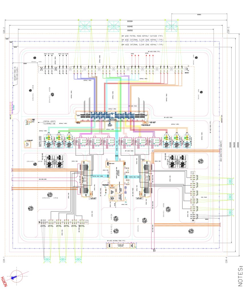
Below Figure Shows a typical Layout Drawing of a 380/132kV BSP. In our upcoming Posts we will provide you with a detail post on each equipment of a BSP. keep Visiting our website.
Related Posts you may like
- Main Components of Substation-Power Transformers
- Panels Required in Substations
- Transmission lines design important points
- Most Common Electrical engineering interview questions
Main Details Shown in Substation/BSP Layout Drawings

1. Substation Boundary & Orientation
- Perimeter fencing or wall with gates.
- North direction clearly marked (compass).
- Plot dimensions and offsets.
2. Gantries and Transmission Line Entries
- 380 kV / 132 kV / 13.8 kV gantries shown at edges of the plot.
- Line terminations with insulators and shield wires.
3. Major Electrical Equipment
- Gas-Insulated Switchgear (GIS) or AIS bays
- Power Transformers (e.g., 380/132 kV, 132/13.8 kV).
- Busbars, disconnect switches, breakers, CTs, VTs, surge arresters.
- Reactors, capacitor banks, synchronous condensers (if applicable).
4. Control & Auxiliary Systems
- Control building (LCC – Local Control Center).
- Battery rooms, DC system, AC services.
- Cable trenches, marshalling kiosks.
5. Roads & Access Routes
- 8 m patrol road (outside) and 6 m internal asphalt roads (as per SEC standard).
- Access for heavy equipment like transformer transporters.
6. Safety & Zoning
- Firefighting routes and hydrants.
- Oil containment pits and oil drainage systems.
- Gravel areas for earthing and step-potential control.
- Clearances:
- Internal clear zone (6 m wide).
- External clear zone (8 m wide).
7. Earthing & Lightning Protection
- Earth mat/grid layout.
- Lightning masts or gantry shield wires.
8. Service Utilities
- Water supply & firefighting system.
- Drainage and sewage.
- Lighting poles, telecom towers, auxiliary transformers.
Why Layout Drawings are Important
- For Design Engineers: To verify clearances, safety zones, and equipment arrangement.
- For Civil Engineers: To plan foundations, cable trenches, and building footprints.
- For Contractors: To execute site construction as per approved design.
- For SEC/Utility Approval: To ensure the design complies with SEC standard drawings and IEEE/IEC requirements.
Top Catogories of our Posts