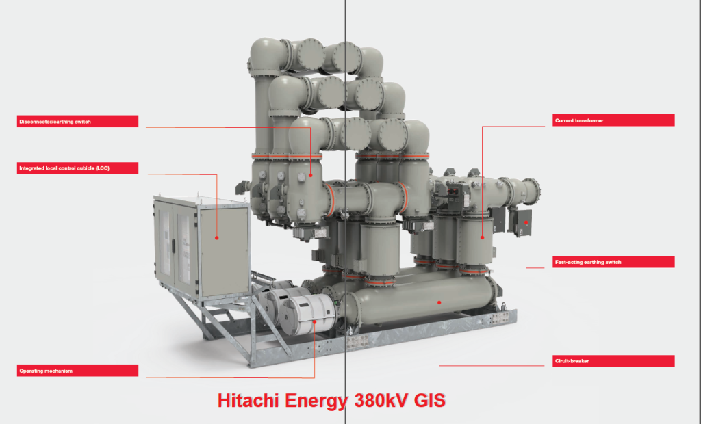
In this post we will provide you an overview of 380kV Gas-Insulated Switchgear (GIS). This is our 3rd post that is part of Extra High Voltage EHV Substation Design & 380kV Substation Design. If you are new on our website it is recommended to read first the below Posts
What is Switchgear?
Switchgear is a general term for the combination of electrical devices used to switch, protect, and control power systems.
- It includes circuit breakers, isolators, relays, fuses, CTs, VTs, busbars, and protective devices.
- The main purpose of switchgear is to interrupt faults, protect equipment, and ensure safe operation of electrical networks.
- Switchgear is used at all voltage levels: LV (Low Voltage), MV (Medium Voltage), HV (High Voltage), and EHV (Extra High Voltage).
In simple terms:
Switchgear = equipment that keeps the power system safe and reliable.
Functions of Switchgear
- Safety → Ensures safe maintenance by providing isolation points.
- Protection → Isolates faulty sections to prevent damage.
- Control → Switches circuits on/off during normal and emergency conditions.
- Measurement → Provides current/voltage signals for metering and protection.
Types of Switchgear
Switchgear can be classified in two main ways:
- Based on Voltage Level
- Based on Insulation/Technology
1. Based on Voltage Level
a) Low Voltage (LV) Switchgear (< 1kV)
- Found in homes, commercial buildings, and industries.
- Components: MCBs (Miniature Circuit Breakers), MCCBs, Contactors, Fuses, RCCBs.
- Example: Distribution boards in residential and industrial systems.
b) Medium Voltage (MV) Switchgear (1kV – 36kV)
- Used in industrial plants, utilities, and secondary substations.
- Components: Vacuum Circuit Breakers (VCB), Ring Main Units (RMU), SF₆ breakers.
- Example: 11kV / 33kV switchgear panels in distribution networks.
c) High Voltage (HV) Switchgear (36kV – 245kV)
- Used in transmission substations and power plants.
- Components: Oil Circuit Breakers, Air Blast CBs, SF₆ CBs.
- Example: 132kV / 220kV switchgear in substations.
d) Extra High Voltage (EHV) & Ultra High Voltage (UHV) Switchgear (>245kV – 765kV)
- Used in bulk transmission and interconnection substations.
- Mostly SF₆ GIS or hybrid systems.
- Example: 380kV, 400kV, 765kV GIS switchgear in transmission BSPs.
2. Based on Insulation / Technology
a) Air-Insulated Switchgear (AIS)
- Equipment installed in open air with large clearances.
- Cheaper but requires large land area.
- Used in remote BSPs and transmission substations.
b) Gas-Insulated Switchgear (GIS)
- All equipment enclosed in SF₆ gas-filled chambers.
- Compact, reliable, but expensive.
- Used in urban substations where space is limited.
c) Hybrid Switchgear
- Combines AIS and GIS.
- Example: GIS for breakers and busbars, AIS for line gantries.
d) Vacuum Switchgear
- Uses vacuum interrupters (mainly for MV systems up to 36kV).
- Compact, safe, and requires minimal maintenance.
e) Oil-Insulated Switchgear (Obsolete in most cases)
- Earlier systems used oil circuit breakers.
- Now replaced by vacuum or SF₆ breakers for safety reasons.
f) SF6-Free GIS (the Future of Switchgear: A Greener, Safer Industry)
- 1. Vacuum + Clean Air Technology
- 2. Fluoronitrile Gas Mixtures
Different types of Switchgear Configurations
In extra high voltage (EHV) and high voltage (HV) substations, the busbar configuration is the heart of reliability. The arrangement of busbars, circuit breakers (CBs), and isolators directly defines how secure, flexible, and costly the substation will be.
In Saudi Arabia’s SEC (Saudi Electricity Company) Bulk Supply Points (BSPs), 380kV substations usually adopt one-and-a-half breaker scheme, while 132kV substations often use double busbar with transfer bus.
Let’s explore each configuration in detail.
1. Single Bus Single Breaker Configuration
Description:
- Each feeder (incoming or outgoing) is connected to one main busbar through a single circuit breaker.
Working:
- Simple arrangement: Line → Circuit Breaker → Bus.
Advantages:
- Cheapest and simplest design.
- Compact layout, minimal land required.
- Easy to operate.
Disadvantages:
- Least reliable: fault on bus = total outage.
- Maintenance requires shutdown of entire section.
- Not suitable for critical loads.
Applications:
- Distribution substations up to 132kV.
- Rare in modern BSPs.
2. Single Busbar with Bus Sectionalizer
Description:
- One busbar is divided into two or more sections, separated by bus sectionalizer (breaker + isolators).
Advantages:
- Fault affects only one section.
- Maintenance possible on one side while other side remains live.
Disadvantages:
- More expensive than single bus.
- Still less flexible than double bus system.
Applications:
- Medium importance substations (132kV).
3. Double Bus Single Breaker Configuration
Description:
- Two main buses (Bus A & Bus B).
- Each feeder connected via one breaker and bus coupler isolators allow transfer between buses.
Advantages:
- High flexibility: feeders can shift between buses.
- Maintenance on one bus possible while other remains live.
- More secure than single bus.
Disadvantages:
- Higher cost (extra isolators, bus system).
- Still, a breaker failure trips that feeder.
Applications:
- 132kV & 220kV substations.
4. Double Bus Double Breaker Configuration
Description:
- Two buses, each feeder has two CBs, one to each bus.
Advantages:
- Very high reliability.
- Fault in bus or breaker does not affect feeder.
Disadvantages:
- Very costly (double CBs for every feeder).
- Complex layout.
Applications:
- Rare; used in highly critical stations (special EHV).
5. Double Bus with Transfer Bus (Breaker-and-a-Half Alternative for AIS)
Description:
- One main bus + one auxiliary (transfer) bus.
- A transfer bus coupler breaker allows load transfer when feeder CB is out for maintenance.
Advantages:
- Allows CB maintenance without feeder shutdown.
- Cheaper than full double bus system.
Disadvantages:
- Only one CB for transfer, limited flexibility.
- If transfer breaker fails, reliability drops.
Applications:
- Very common in 132kV AIS substations (Saudi SEC standard).
6. Ring Bus Configuration
Description:
- Circuit breakers form a ring, each node connecting to a line or transformer.
- Each circuit is between two CBs.
Advantages:
- Fault affects only one section, rest remain live.
- Higher reliability than double bus.
- Requires fewer CBs than one-and-a-half scheme.
Disadvantages:
- Expansion is difficult.
- Protection system is more complex.
Applications:
- 220kV & 380kV substations, but not common in SEC.
7. One-and-a-Half Breaker Scheme
Description:
- Every two feeders share three CBs (1.5 CB per circuit).
- Each feeder connected between two buses with shared breakers.
Advantages:
- Most reliable & flexible.
- Fault in any bus or breaker does not interrupt supply completely.
- Allows full redundancy and easy maintenance.
Disadvantages:
- High cost, more CBs and protection relays required.
- Complex operation.
Applications:
- Standard for 380kV Bulk Supply Points (BSPs) in Saudi Arabia.
- Critical transmission networks worldwide.
8. Mesh Bus Configuration
Description:
- CBs arranged in a mesh (grid), each junction connects to feeders.
Advantages:
- Very high security and flexibility.
- Faults isolated locally.
Disadvantages:
- Very complex protection system.
- Expensive and difficult to expand.
Applications:
- Rare; only in extremely critical UHV substations.
Comparison Table of Switchgear Configurations
| Configuration | Reliability | Cost | Expansion | SEC Usage |
|---|---|---|---|---|
| Single Bus Single Breaker | Low | Low | Easy | No |
| Single Bus + Section | Medium | Low | Medium | Limited |
| Double Bus Single Breaker | High | Medium | Medium | Yes (132kV) |
| Double Bus Double Breaker | Very High | Very High | Hard | Rare |
| Double Bus + Transfer Bus | High | Medium | Easy | Yes (132kV) |
| Ring Bus | Very High | Medium-High | Difficult | Rare |
| One-and-a-Half Breaker | Excellent | High | Easy | Standard 380kV BSP |
| Mesh Bus | Excellent | Very High | Very Hard | Very Rare |
According to Section 5.10 of the TES-P-119.19, Rev. 03 document, the minimum side clearances inside a 110 kV GIS building are as follows:
Next Post Topic
Important points from Saudi Electricity Conmpany Standards regarding 380kv & 132kv GIS