Autotransformers are among the most misunderstood yet critically important assets in modern power systems. While they appear deceptively simple at low voltages, at EHV levels (380–500 kV) they become system-defining components that directly influence fault levels, insulation coordination, grounding, and grid stability.
This article provides a complete, utility-grade explanation of autotransformers, covering theory, mathematics, IEC standards, and real-world design practice.
1. What Is an Autotransformer?
An autotransformer is a transformer in which part of the winding is common to both the primary (source) and secondary (load).
Unlike a conventional two-winding transformer:
- There is no galvanic isolation
- Power is transferred by:
- Magnetic induction
- Direct electrical conduction
This fundamental difference is the reason autotransformers are:
- Smaller
- More efficient
- Cheaper
—but also more demanding from a system-engineering perspective.
This is our 7th post that is part of Extra High Voltage EHV Substation Design & 380kV Substation Design. If you are new on our website it is recommended to read first the below Posts
- 380kV Gantries & Gantry Equipment
- Inside a 380kV BSP: Overall Layout Drawing Explained
- 380kV Gas-Insulated Switchgear (GIS)
- Power Transformers
- Auxiliary Transformer Sizing for a 380kV BSP
- Vector Group of Transformers
2. Autotransformer vs Two-Winding Transformer
| Aspect | Two-Winding | Autotransformer |
|---|---|---|
| Electrical isolation | Yes | No |
| Power transfer | Induction only | Induction + conduction |
| Size & weight | Larger | Smaller |
| Losses | Higher | Lower |
| Fault level control | Better | Poorer |
| Typical use | Distribution | HV / EHV interties |
3. Step-Up and Step-Down Autotransformers
Step-Up Autotransformer
- Load voltage > Source voltage
- Series winding in series with load
- Common winding shared
Step-Down Autotransformer
- Load voltage < Source voltage
- Series winding in series with source
- Common winding shared
At EHV level, both operate on the same principle — only scale and risk change.
4. Key Parts of an Autotransformer
Common Winding
- Electrically shared
- Transfers power inductively
- Carries difference of currents
Series Winding
- Carries full line current
- Transfers power conductively
This division directly impacts:
- Thermal design
- Short-circuit withstand
- Protection philosophy
5. Power Transfer Mathematics (Core Concept)
Total apparent power is divided into:
Transformed (Inductive) Power
Strans=S×VHVVHV−VLV
Conducted Power
Scond=S−Strans
Only the transformed portion requires full magnetic coupling, which explains the material and efficiency advantage.
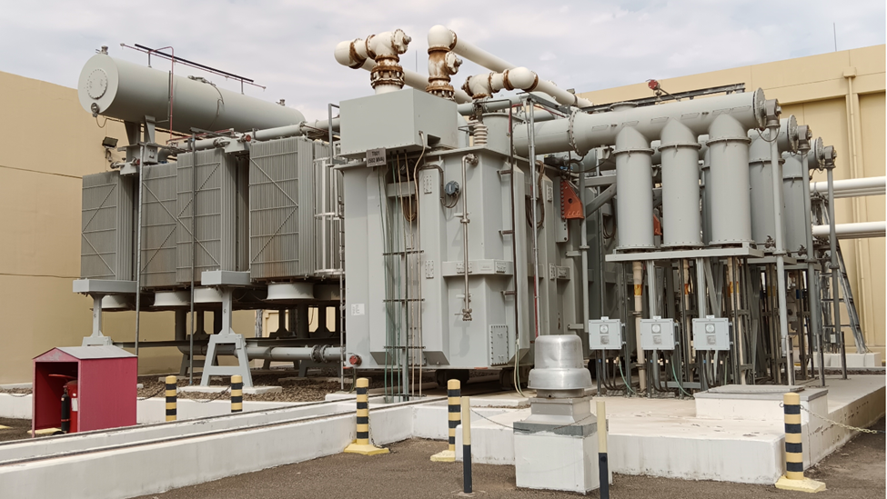
6. Example: 380 / 132 kV – 502.5 MVA Autotransformer
Line Currents
380 kV sideI380=3×380×103502.5×106=763 A
132 kV sideI132=3×132×103502.5×106=2198 A
Power Split
Strans=502.5×380380−132=328 MVA Scond=174.5 MVA
➡ Only ~65% of power is magnetically transformed
7. Autotransformers & IEC 60076
IEC 60076 fully governs autotransformers:
- IEC 60076-1 – Ratings & general requirements
- IEC 60076-2 – Temperature rise
- IEC 60076-3 – Insulation & dielectric tests
- IEC 60076-5 – Short-circuit withstand
- IEC 60076-8 – Application guide
IEC clearly states:
The rated power of an autotransformer is the total apparent power, provided winding current limits are not exceeded.
8. Why Utilities Use Autotransformers at 380–500 kV
Autotransformers dominate EHV grids because:
- Voltage ratio is relatively small (e.g. 500/380, 400/220)
- Two-winding transformers become impractical
- Material and transport constraints dominate
- Efficiency > 99.7%
A 500/380 kV two-winding transformer would be:
- Much larger
- ~30–40% more expensive
- Harder to transport
9. Vector Group Explained – YNa0d1
For a 380/132/13.8 kV autotransformer:
- Y – Star HV winding
- N – Neutral brought out
- a – Autotransformer (common winding)
- 0 – 0° phase shift between 380 & 132 kV
- d1 – Delta tertiary, 30° phase displacement
This configuration ensures:
- Grid synchronism
- Harmonic suppression
- Zero-sequence control
10. Delta Tertiary (13.8 kV) – Why It Exists
The tertiary winding is not optional.
Functions:
- Absorbs 3rd harmonics
- Provides zero-sequence path
- Stabilizes voltage during unbalanced faults
- Supplies:
- Shunt reactors
- Station service
- FACTS devices
Typical rating: 30–40% of main MVA
11. Grounding Philosophy (Critical at EHV)
Because there is no isolation:
- Ground faults propagate between voltage levels
- Neutral grounding defines fault current magnitude
Common practice:
- Neutral grounded via reactor
- Sometimes resistance grounded
- Rarely solid at EHV
12. Protection Challenges of Autotransformers
Autotransformer protection is significantly more complex than two-winding transformers.
Mandatory protections:
- Biased differential (87T)
- Restricted earth fault (REF)
- Overfluxing (V/Hz)
- Neutral displacement
- Buchholz
- Sudden pressure
- Temperature supervision
CT placement and zero-sequence compensation are design-critical.
13. Insulation Coordination & Surge Transfer
Key reality:
Lightning and switching surges on HV side partially appear on LV side.
Design implications:
- LV insulation levels are increased
- Surge arresters required on all windings
- Coordination per IEC 60071
14. Fault Levels & System Impact
Autotransformers:
- Have low impedance (typically 12–18%)
- Do not block fault current
- Increase short-circuit levels at lower voltage
This affects:
- GIS ratings
- Circuit breaker duty
- Busbar design
15. Advantages of Autotransformers
✔ Higher efficiency
✔ Lower cost
✔ Smaller size
✔ Higher MVA capability
✔ Ideal for EHV interties
16. Disadvantages & Risks
❌ No electrical isolation
❌ Higher fault currents
❌ Surge transfer risk
❌ Complex protection
❌ Common winding failure impact
17. Where Autotransformers Should NOT Be Used
- Large voltage ratios (e.g. 380/13.8 kV)
- Distribution systems requiring isolation
- Systems with strict fault-level limits
In such cases, two-winding transformers are mandatory.
18. Final Expert Takeaway
An autotransformer is not just a transformer — it is a grid-coupling element.
At EHV level, success depends on:
- Mathematics
- Insulation coordination
- Protection engineering
- Grounding design
- IEC compliance
When designed correctly, an autotransformer delivers:
✔ Efficiency
✔ Reliability
✔ Long service life (>40 years)
When misunderstood, it becomes a system risk.