High-voltage power systems like 380kV transmission lines are the backbone of modern grids. They carry electricity over long distances, and any fault (like a short circuit or flashover) the system must detect it instantly and isolate it to protect equipment and keep the grid stable. That’s where feeder protection signaling comes in.
In this post, we’ll break down how Saudi Electricity Company (SEC) typically applies protection signaling for 380kV feeders — and why it’s so important.
380kV Feeder Protection Signaling is a part of our series of posts on Substation Layout Drawing & Explanation each equipment in a 380kV BSP. Below are some of our most read posts
- Inside a 380kV BSP: Overall Layout Drawing Explained
- 380kV Gantries & Gantry Equipment
- List of Contractors who Won Major BSP Projects in 2024 in KSA
- Tower Testing in Power Transmission: A Complete Guide
- Top Electrical Engineering Courses on Coursera
- List of Top Substation contractors in KSA
- Vector Group of Transformers
- Top Excel Functions Every Engineer Should Master
Protection Signaling
Protection signaling is the exchange of information between protection relays located at both ends of a transmission line (or feeder), using a communication channel, to ensure faults are detected and cleared quickly, selectively, and reliably.
In simpler terms:
It’s the “conversation” between relays that allows them to agree when and how to trip a circuit breaker in case of a fault. you can also define it as
💡 “Protection signaling is the fast, secure exchange of trip and block commands between relays at both ends of a transmission line, ensuring faults are cleared instantly and reliably.”
Why Do We Need Protection Signaling
- A transmission line has two ends (Substation A and Substation B).
- A fault (short circuit, flashover, etc.) may occur anywhere along the line.
- For fast and selective tripping, the relays at both ends must coordinate.
- Protection signaling ensures this coordination by sending trip/block/permit signals in real time.
Methods of Protection Signaling
Protection signals usually we transmit via:
- Direct Optical Fiber Channels
- MPLS-TP Networks
- Power Line Carrier Communication (PLCC) (for longer distances)
- Microwave links / Digital Radios (in some cases)
How the Protection Signaling Process Works
Protection signaling is a step-by-step process that ensures any fault in a high-voltage transmission line is detected and cleared within milliseconds. Here’s how it works:
- Sensing: Current transformers (CTs) and potential transformers (PTs) measure high-voltage currents and voltages. Reduces them to safe levels for protective relays.
- Detection: The protective relay constantly monitors the inputs from the CTs and PTs. If it detects an electrical anomaly that exceeds pre-set thresholds, it identifies the location and type of fault.
- Signaling: The relay sends a trip signal, typically a direct-current (DC) pulse from a reliable battery backup, to the appropriate circuit breaker.
- Isolation: The circuit breaker, upon receiving the trip signal, physically interrupts the flow of electricity to isolate the faulty section.
- Logging: The relay logs the event and other diagnostic data, which is often sent to a central Supervisory Control and Data Acquisition (SCADA) system for analysis.
SEC 380kV Feeder Protection Signaling Typical
The below figure shows a typical protection signaling diagram for a 380kV single power feeder as per SEC standards.
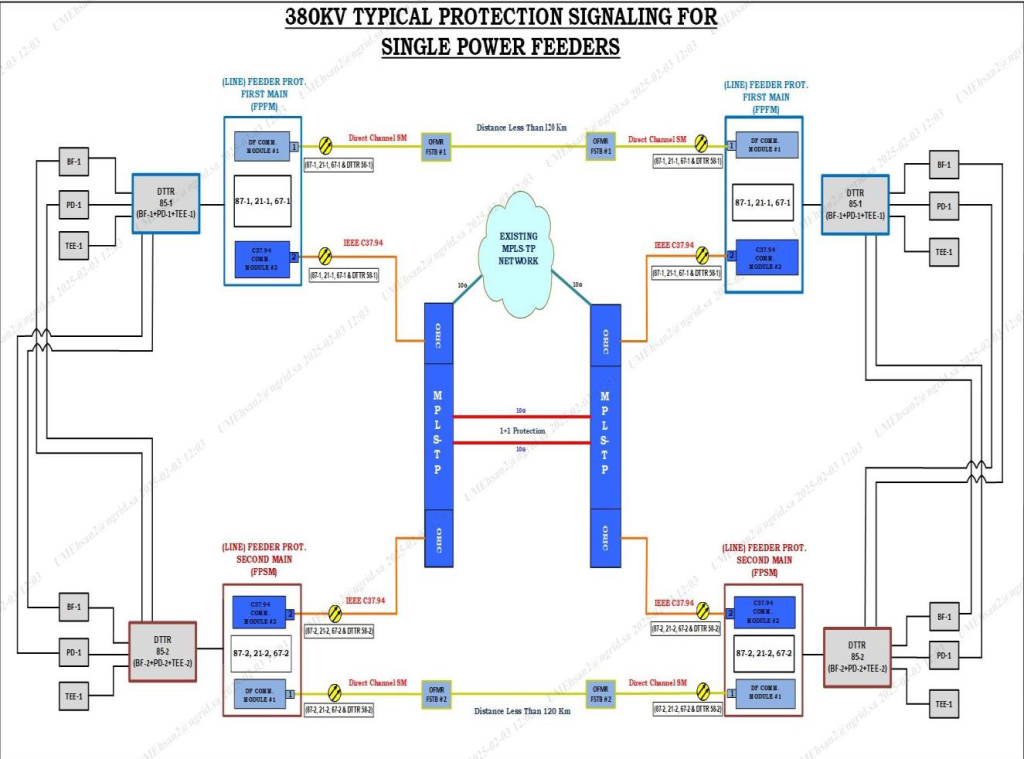
Main Components:
As per above figure, following are the main components of 380kV Feeder Protection Signaling
- DTTR (Double Trip Relay) 851 & 852
- Connected to Busbar Feeder (BF), Potential Device (PD), and Transmission Line Tee (TEE).
- DTTR-851 is linked with First Main Protection (FFPM).
- DTTR-852 is linked with Second Main Protection (FPSM).
- Line Feeder Protection Schemes:
- First Main (FFPM) – Top section in blue boxes.
- Second Main (FPSM) – Bottom section in red boxes.
- Relay & Protection Functions:
- 87 – Differential Protection
- 21 – Distance Protection
- 67 – Directional Overcurrent Protection
- 21-1, 21-2 – Zone 1, Zone 2 distance protections
- DF COM. MODULE #1
- C37.94 COM. MODULE #2
- Communication & Signaling:
- Direct Channel SM (Substation Multiplexer) → handles point-to-point signals.
- IEEE C37.94 → Optical communication interface for relays.
- OFMR FSTB → Optical Fiber Modem with Redundancy.
- MPLS-TP Network → Provides backbone communication with 1+1 Protection, ensuring redundancy.
Working Principle:
- Main-1 Protection (Blue) and Main-2 Protection (Red) operate independently to ensure redundancy.
- Each main protection sends tripping and signaling commands via:
- Direct Fiber Channel (short distance)
- MPLS-TP (packet transport network with redundancy)
- The system ensures fast fault clearance and secure backup protection for 380kV feeders.