Selecting the right cable size is important for both safety and efficiency. An undersized cable may overheat, cause voltage drops, or even lead to fire hazards. An oversized cable increases cost unnecessarily.
Cable size is selected based on the following key factors:
Current Carrying Capacity (Ampacity):
The cable must handle the full-load current of the motor or load without overheating. Ampacity is the maximum current a cable can safely carry without exceeding its temperature limit, which could damage insulation or reduce the cable’s lifespan.
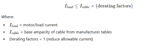
Cable ampacity must be greater than or equal to the expected load current. which is given as
Voltage Drop:
Voltage drop is the reduction in voltage that occurs when electrical current flows through a cable due to its resistance and reactance.
If voltage drop is too high, motors and equipment may not receive enough voltage, leading to:
- Poor performance (motors may not start properly).
- Overheating and reduced lifespan.
- Energy losses.
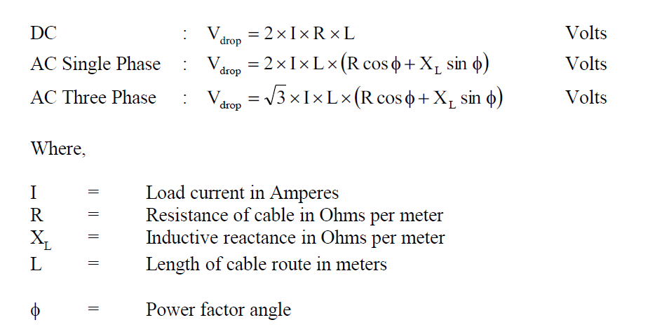
Ensure the voltage drop is within permissible limits (usually ≤3–5%) to maintain proper performance. As per SEC Standards the formula for Voltage drop is
Short-Circuit Rating:
The short-circuit rating of a cable is the maximum current the cable can safely carry for a short duration (usually 1 second) during a fault without being damaged.
This ensures that the cable insulation and conductor can withstand the heat generated by fault currents.
Formula (IEC Standard):
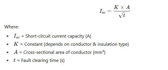
Typical K Values (Copper Cables):
- PVC insulation → 115
- XLPE insulation → 143
The cable must withstand the thermal and mechanical stresses during short-circuit conditions.
Why Important?
- If short-circuit rating is lower than fault current, the cable may melt or catch fire.
- Cable size must match both continuous load current (ampacity) and fault withstand capacity.
Derating Factors:
Derating factors are correction multipliers (<1) applied to the base current-carrying capacity of a cable to account for real installation conditions (heat, grouping, soil, etc.).
They ensure the cable doesn’t overheat under practical site conditions.
Key Derating Factors
Buried, in conduit, in tray, exposed, etc. Each has a different cooling condition.Consider ambient temperature, grouping of cables, soil conditions (for underground cables), and installation method.
Ambient Temperature (Air/Soil):
- Higher temperatures reduce cooling of cables.
- Example: If ampacity = 200 A, and derating factor = 0.85 → effective ampacity = 170 A.
Grouping of Cables:
- Multiple cables together = less heat dissipation.
- Correction factor applied depending on number of cables in a tray/conduit.
Soil Thermal Resistivity (for underground cables):
- Poor soil conductivity = higher cable heating.
- Standard is 1.2 K·m/W; worse soil = lower derating factor.
Installation Method:
Buried, in conduit, in tray, exposed, etc. Each has a different cooling condition.
Our most read Posts you may like are as follows
- Top Electrical Engineering Courses on Coursera
- Transmission Line Design Important Points
- Panels required inside substations
- Electrical MCQs with Explanation of Answers
- Electrical Past papers
- How to Add MCQs in wordpress posts
- Transmission Lines design Basics
- Inside a 380kV BSP: Overall Layout Drawing Explained
- 380kV Gantries & Gantry Equipment
- List of Contractors who Won Major BSP Projects in 2024 in KSA
- Tower Testing in Power Transmission: A Complete Guide
- Top Electrical Engineering Courses on Coursera
- List of Top Substation contractors in KSA
- Vector Group of Transformers
- Top Excel Functions Every Engineer Should Master
Standards & Codes:
Refer to IEC/NEC standards and local utility requirements (e.g., SEC in Saudi Arabia) for compliance.
Permissible Limits (as per IEC & NEC ):
- Lighting circuits: ≤ 3%
- Power & motor circuits: ≤ 5%
SEC Standard for LV Cable Sizing
TES-P-119.29 R1 is used for low voltage rating of 600/1000 V power cables sizing calculation. As per this Standard, the allowable voltage drop shall be limited to 5 % of the system nominal voltage throughout, from the supply sources to the load ends
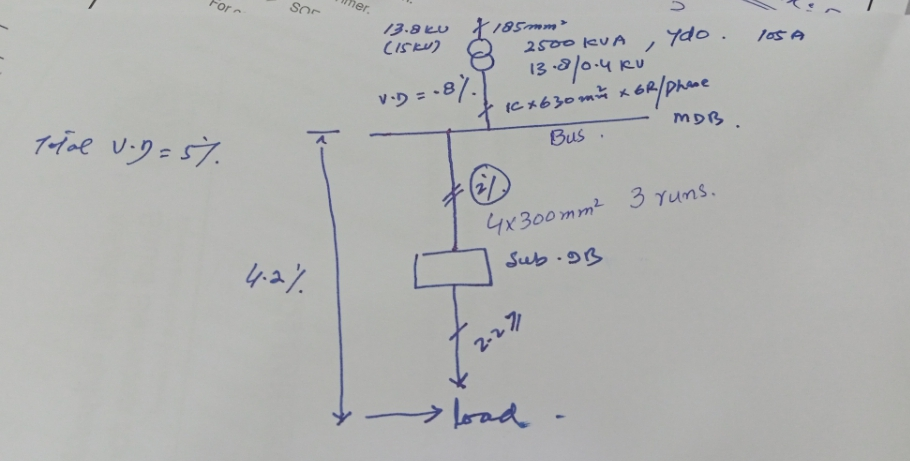
The following are the limits of voltage drop considered for design :
- Station transformer to main distribution board (MDB) 0.8%
- ACDB to loads – 4.2%
- DCDB to control/relay panel 0.4%
- ACDB to Sub distribution panel / Lighting panel – 3.5%
- Sub distribution Panel to loads – 0.7%
- Lighting Panels to loads – 0.7%