Single Line Diagrams (SLDs) can look intimidating at first. Rows of switches, transformers, and feeder numbers fill a single sheet. But once you understand the logic behind the layout, an SLD tells a clear story. It shows how power comes in, how the system protects it, how transformers step it down, and how it finally reaches the loads.
In this post, we’ll walk through a real-world example. It’s a 115kV/13.8kV substation typical of industrial and utility installations in Saudi Arabia’s Eastern Region. This kind of substation usually sits between the main 115kV transmission network and a plant’s medium-voltage distribution system.
This post is also a part of Extra High Voltage EHV Substation Design & 380kV Substation Design. If you are new on our website and want to learn 380kV Level, it is recommended to read first the below Posts
- 380kV Gantries & Gantry Equipment
- Inside a 380kV BSP: Overall Layout Drawing Explained
- 380kV Gas-Insulated Switchgear (GIS)
- Power Transformers
- Auxiliary Transformer Sizing for a 380kV BSP
- Vector Group of Transformers
- Autotransformers
1. The Big Picture: Two Voltage Levels, One Purpose
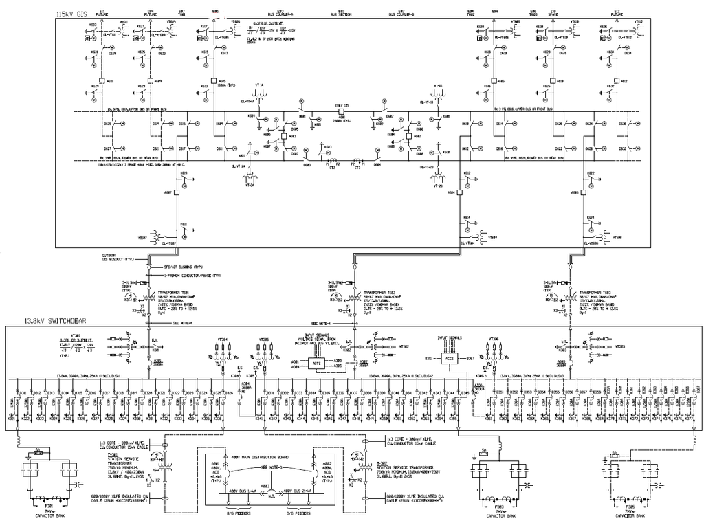
At a glance, this SLD splits into three horizontal layers:
- Top section — 115kV GIS (Gas Insulated Switchgear): the incoming high-voltage side
- Middle section — Power Transformers: stepping 115kV down to 13.8kV
- Bottom section — 13.8kV Switchgear: the medium-voltage distribution system that feeds outgoing loads, station auxiliaries, and capacitor banks
This top-to-bottom flow — HV in, step down, MV out — is the standard architecture for a substation feeding an industrial plant, utility load center, or a large facility such as a refinery, water treatment plant, or district cooling site.
2. The 115kV GIS Bus System
The top of the drawing shows the 115kV Gas Insulated Switchgear. Engineers choose GIS over open-air (AIS) switchgear for a simple reason: it needs a much smaller footprint. It also protects the equipment better against dust and humidity, which makes it a common choice for Eastern Province substations where space and environmental exposure both matter.
Look closely at the bus arrangement and you’ll notice a double bus system with bus coupler bays:
- Upper bus (Front Bus) and Lower bus (Rear Bus) run the full width of the panel
- A Bus Section breaker splits the system into two halves
- Bus Coupler-A and Bus Coupler-B let operators transfer any feeder from one bus to the other
This is the classic “double bus, single breaker with bus coupler” philosophy. For operations, it means flexibility: if one bus or breaker needs maintenance, the system can transfer load to the other side without a full outage. For a contractor building this, it also means more primary equipment — extra breakers, extra disconnectors — and more space for bus duct routing. Flag this early during layout and civil coordination.
Along the bus, you’ll notice several bay types:
- Future bays — spare positions reserved for expansion. Crews wire these into the bus structure so a new feeder can join later without disturbing the live system.
- Feeder bays — outgoing 115kV lines to other substations or loads
- Transformer feeder bays — dedicated bays feeding the two step-down transformers
Each bay follows a repeating pattern: disconnect switches, circuit breakers, current transformers (CTs), and earthing switches. These are the standard building blocks of any GIS bay. GIS just packages them compactly inside gas-insulated modules instead of open-air structures. if you want to learn GIS in details visit our post on Gas Insulated Switchgears
3. The Power Transformers: The Heart of the Substation
Two power transformers step the voltage down from 115kV to 13.8kV. The nameplate data on the drawing shows:
- Rating: 50/67 MVA, ONAN/ONAF cooling — natural cooling under normal conditions, with fans engaging under higher load
- Voltage ratio: 115/13.8 kV
- On-Load Tap Changer (OLTC): roughly -20% to +12% range. This lets the transformer automatically adjust its ratio and keep the 13.8kV bus voltage stable as grid conditions or load change.
Why run two transformers instead of one? It’s a deliberate reliability choice. If one transformer trips or needs maintenance, the other can pick up the critical load, often with some load-shedding on non-essential feeders. This mirrors the same N-1 redundancy logic used at the bus level, just applied to the transformation stage.
From an execution standpoint, the transformer bay is usually one of the most coordination-heavy parts of a substation build. GIS bus duct connections on the HV side, cable trenches or bus duct on the LV side, oil containment and fire walls, and the transformer’s own cooling and protection systems — Buchholz relay, temperature indicators, pressure relief — all need to come together before energization testing.
4. The 13.8kV Switchgear: Where the Power Gets Distributed
This is the busiest part of the drawing, and for good reason: it’s where the substation actually delivers power to the plant or facility.
The 13.8kV bus splits into three sections (Section Bus-1, Bus-2, Bus-3), each rated 3600A, connected through bus tie breakers. This sectionalized arrangement means a fault or maintenance activity on one section won’t take down the entire medium-voltage system. Only the affected section loses power, and tie breakers can restore supply from an adjacent section when needed.
Along each section, a long row of numbered outgoing feeders (in the K3xx / K3xxx range) feeds the actual downstream loads — motor control centers, further step-down transformers, or other distribution panels within the facility. The sheer number of feeders here is typical for a plant-level substation supporting many process areas or buildings.
A few supporting elements deserve a mention on the 13.8kV side:
- Voltage transformers (VTs) feed metering and protection relay input signals from the incomer and bus sections.
- Protective relay signal wiring, shown schematically near the bus sections, feeds the substation’s protection and control system.
5. Station Auxiliary Power System
No substation runs on its own high-voltage supply for internal needs like lighting, control power, HVAC, and battery chargers. Instead, dedicated station service transformers step 13.8kV down further to 480V/230V for house loads.
In this SLD, you can see:
- Station service transformers, 750kVA, 13.8kV/480-230V, feeding a 480V Main Distribution Board (MDB)
- The MDB splits into 480V Bus-1 and Bus-2, again tied together for redundancy
- Diesel Generator (D/G) feeders connected to the 480V system, providing backup power if the main incoming supply fails
This backup matters because it keeps protection, control, and communication systems alive during an outage. The auxiliary system is small in capacity compared to the main transformers, but it’s operationally critical. If it fails, the substation can lose its ability to monitor and control itself, even when the main power path stays intact.
For more details you can visit
6. Capacitor Banks: Keeping the Power Factor in Check
At both ends of the 13.8kV switchgear, you’ll see capacitor banks (labeled F301, F303, F305), each rated around 7 MVAR and connected through their own switching arrangement and fuses.
Capacitor banks correct the power factor of the system by offsetting the reactive power that large inductive loads — motors and transformers — draw. Without them, the utility supply would carry more current than necessary to deliver the same real power. That leads to higher losses and, often, financial penalties from the utility for poor power factor.
7. Why This Architecture Makes Sense
Step back and you’ll notice a consistent theme running through the whole design: redundancy at every stage.
- Double bus with bus coupler at 115kV
- Two parallel transformers
- Sectionalized 13.8kV bus with tie breakers
- Dual 480V auxiliary buses with D/G backup
This layered redundancy is standard practice for substations serving continuous-process industries — oil & gas, petrochemical, water and desalination, and similar facilities common across the Eastern Province. In these settings, an unplanned outage can be extremely costly or even unsafe.
8. A Note for Contractors and EPC Teams
For anyone executing a build like this, the SLD works as the master reference. Everything else — cable schedules, protection coordination studies, relay settings, and construction sequencing — gets derived from it. Here are a few practical takeaways:
- GIS bay count and future spares directly drive the switchgear building footprint and civil works scope. Confirm these early, since GIS buildings are expensive to modify later.
- Transformer bay clearances and fire barriers need coordination between electrical, civil, and fire protection disciplines from the start.
- Feeder count on the 13.8kV switchgear (dozens of outgoing circuits here) means cable routing, trenching, and termination scope should be quantified early. This is often where schedule risk hides.
- Auxiliary power and D/G backup should be commissioned and tested independently before main system energization, since protection and SCADA systems depend on it being reliable first.
Ultimately, reading the SLD this way — as a map of construction sequence, testing dependencies, and reliability philosophy, not just a drawing — is what separates reading a diagram from actually executing the project it describes.