Two transformers can have the same voltage ratio and MVA rating, yet force different decisions about switchgear, motor starting, parallel operation and future expansion. The difference may be a small entry on the datasheet: short-circuit impedance.
This article investigates three hypothetical 132/13.8 kV, 50 MVA transformers with 10%, 15% and 20% impedance. It follows the consequences from fault-current calculations through voltage performance and EPC procurement. The aim is to identify a feasible design window, rather than declare one percentage universally best.
Research and method: original worked examples supported by manufacturer guidance and official IEC publication references, reviewed 15 November 2026. Examples are educational screening calculations, not a completed utility design or a full IEC 60909 study. Assumptions change between examples and are stated where used.
Affiliate disclosure: this article includes a clearly identified Udemy affiliate link in the optional professional-development section. We may earn a commission if you purchase through it.
Navigate: Meaning and bases · Fault-current comparison · Voltage performance · Parallel operation · Motor starting · Three windings · EPC cost · Procurement checklist · References
The design trade-off in one view
| Increasing impedance, with other assumptions controlled | Likely consequence | What to verify |
|---|---|---|
| Transformer-fed three-phase fault current | Decreases | Other sources, minimum/maximum network strength and full fault duty. |
| Voltage drop at lagging load power factor | Usually increases when reactance increases | R/X components, tap range, source voltage and actual load model. |
| Motor starting voltage | May fall further | Motor torque, acceleration time, existing loads and starting method. |
| Parallel load sharing | Lower-impedance unit carries a larger share under matching-ratio assumptions | Impedance bases, impedance angles, feeder links and tap control. |
| Total installed cost | Can move in either direction | Complete compliant design, OEM quotations and lifecycle evaluation. |

1. What does 15% transformer impedance actually mean?
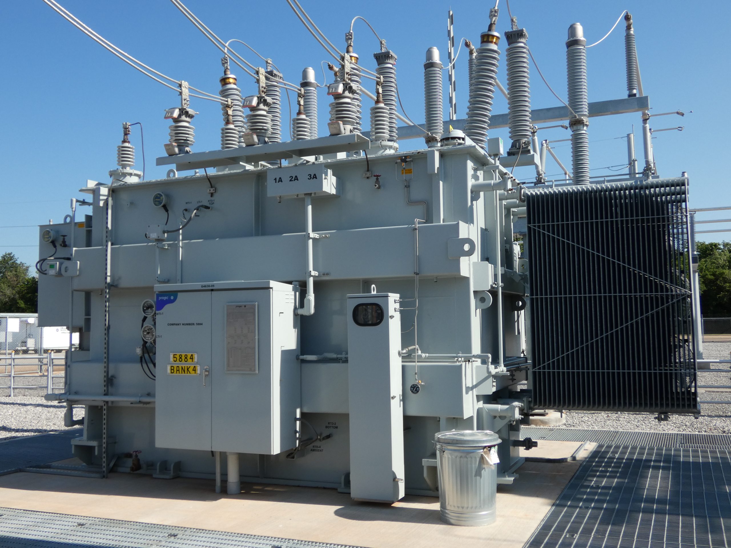
Short-circuit impedance is the equivalent series impedance of a specified pair of windings, measured at rated frequency and a stated reference temperature. The other winding of the pair is shorted; any additional windings are open. The value also belongs to a particular tap position. Schneider Electric’s definition makes these conditions explicit. [1]
In the short-circuit test interpretation, 15% impedance means approximately 15% of the applicable rated voltage is needed to circulate rated current with the paired winding shorted under the specified test conditions. It does not mean 15% of normal operating power is lost, or that the loaded secondary voltage always drops by 15%.
Z = R + jX; |Z| = √(R² + X²). Resistance represents the equivalent active-loss component at the chosen conditions; leakage reactance describes the effect of flux that does not link both windings. A high reactance is not an equivalent percentage of heat loss.
For a balanced three-phase system, using line-to-line voltage and three-phase MVA consistently: Zbase = Vbase²/Sbase, zpu = Z/Zbase, and Z% = 100 × zpu. With kV and MVA, Zbase is in ohms per phase.
On the 13.8 kV, 50 MVA base, Zbase = 13.8²/50 = 3.8088 Ω. Therefore 10%, 15% and 20% correspond to 0.38088 Ω, 0.57132 Ω and 0.76176 Ω, referred to that side. The physical ohmic values referred to the 132 kV side differ by the square of the turns ratio.
A percentage without a base can mislead
Convert values before comparing them: znew = zold × (Snew/Sold) × (Vold/Vnew)², with voltages referring to the same physical winding. If the voltage base is unchanged, 15% on 50 MVA becomes 30% on 100 MVA. The transformer has not physically changed.
Cooling ratings also matter. If an impedance is declared on one MVA base, do not silently reuse the same percentage on a higher forced-cooling rating. Rebase the data and obtain the guaranteed test conditions. See our transformer cooling and multiple MVA ratings guide.
2. Fault-current comparison: 10%, 15% and 20%
Rated secondary current is In = S/(√3V) = 50/(√3 × 13.8) = 2.09185 kA. For a bolted three-phase secondary fault and a negligibly small upstream impedance, the simple transformer-limited relationship is Isc ≈ In/zpu. Schneider’s installation guide uses this simplified approach for transformer-secondary calculations. [2]
| Transformer impedance | Infinite-source screening current | Transformer-limited fault level |
|---|---|---|
| 10% | 20.92 kA | 500.0 MVA |
| 15% | 13.95 kA | 333.3 MVA |
| 20% | 10.46 kA | 250.0 MVA |
These figures use nominal voltage, c = 1 and no additional infeed. They are symmetrical RMS screening values. They do not specify peak making current, DC offset, breaking current at contact separation, short-time withstand or an earth-fault current.
Include the upstream source
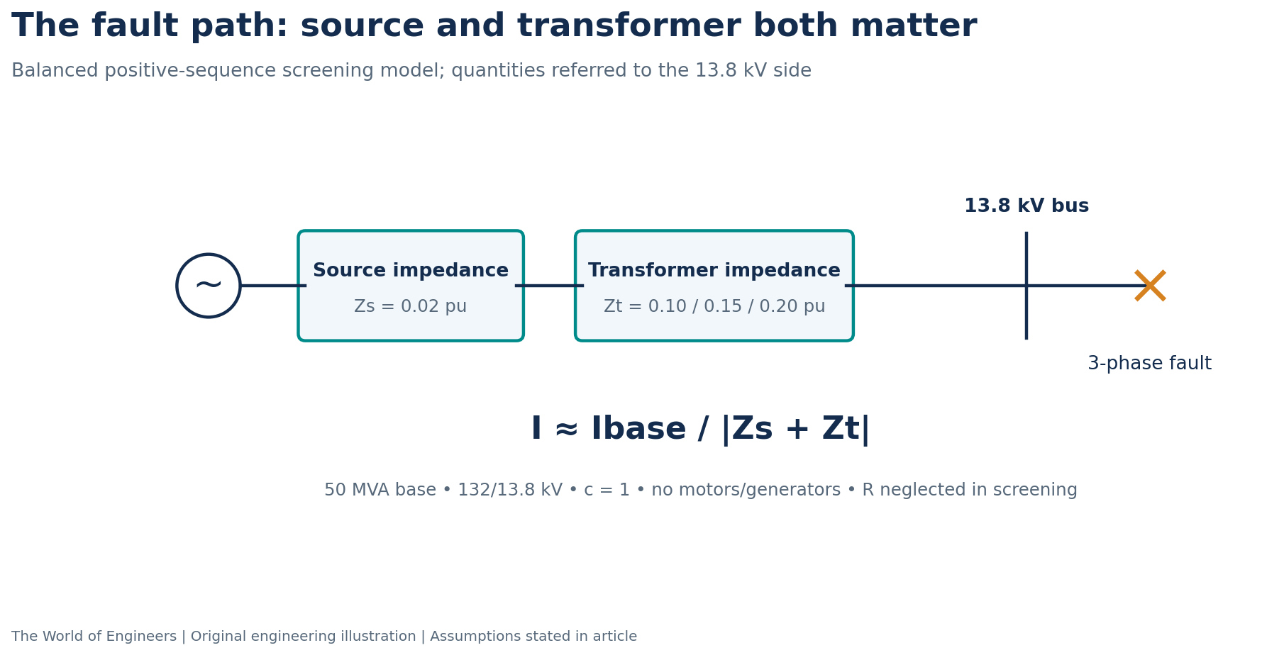
Assume a 2,500 MVA short-circuit level at the 132 kV source bus. On the 50 MVA base its impedance magnitude is approximately 50/2,500 = 0.02 pu. For the next screening table, neglect resistance and treat the source and transformer impedances as aligned inductive quantities.
Then Isc ≈ 2.09185/(zT + 0.02). In a detailed calculation, combine the complex R+jX values; adding unrelated impedance magnitudes is not generally valid. Schneider’s guide describes combining the upstream network and component impedances. [3]
| Transformer Z | Total screening Z | Current with 2,500 MVA source |
|---|---|---|
| 10% | 0.12 pu | 17.43 kA |
| 15% | 0.17 pu | 12.30 kA |
| 20% | 0.22 pu | 9.51 kA |
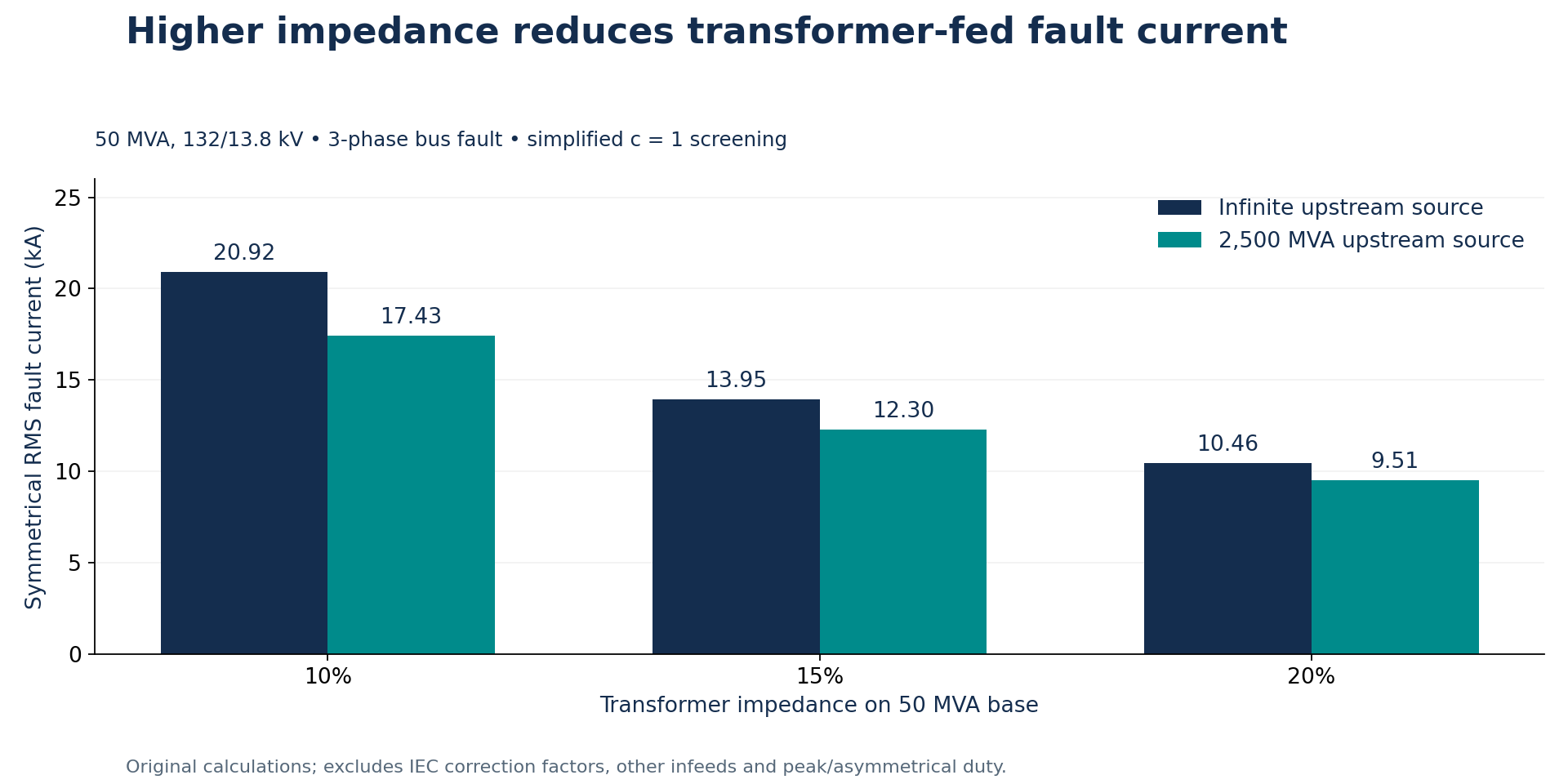
For the 15% option, ignoring the source raises the estimate from 12.30 to 13.95 kA—about 13.3% above the finite-source result. Whether that difference changes an equipment decision depends on the complete maximum-fault case and the available rating margins.
Why the quick formula cannot select your breaker
A common source impedance must be represented correctly when transformers are paralleled. Do not simply double a finite-source result if both transformers share that upstream source. Include motors, generators, converter contributions, bus couplers, future circuits and the relevant network topology.
Use the contractually applicable calculation method. The IEC webstore identifies IEC 60909-0:2026 as the current published edition reviewed for this article. Its existence does not automatically change the edition incorporated into an existing contract. [8]
Check maximum and minimum cases separately. Low impedance is critical for maximum transformer-fed current; high impedance and weak-source conditions can be critical for protection sensitivity and voltage performance. Use the prescribed voltage factors, transformer corrections, tolerances and operating conditions in the formal study.
3. Voltage performance: why 15% impedance is not 15% voltage drop
For a first-order estimate at current fraction k and a lagging power factor cosφ: ΔVpu ≈ k(rpu cosφ + xpu sinφ). The reactive term changes sign for a leading current. This is a phasor approximation, not a universal exact load-flow result. Manufacturer guidance discusses how resistance, reactance and power factor affect regulation. [9]
For this independent sensitivity example, hold the equivalent resistance at r = 0.005 pu for all three designs, set x = √(z² − r²), and use rated current, 0.90 lagging power factor, a 1.0 pu ideal source and a fixed tap. This isolates the influence of leakage reactance; it is not a guarantee that three OEM designs have identical losses.
| Z | X on 50 MVA base | First-order voltage fall | Series-circuit phasor voltage fall |
|---|---|---|---|
| 10% | 9.9875% | 4.80% | 5.19% |
| 15% | 14.9917% | 6.98% | 7.87% |
| 20% | 19.9937% | 9.17% | 10.76% |
The last column solves the stated series circuit at fixed rated current and fixed power factor relative to the receiving voltage: v = √[1 − (x cosφ − r sinφ)²] − (r cosφ + x sinφ). Voltage fall is (1−v)×100%. Magnetising current, upstream impedance, tap action and load-voltage dependence are omitted.
This additional check matters because a first-order estimate becomes less accurate as impedance grows. A constant-MW/MVAR load draws a different current as voltage falls; it needs a proper load-flow solution. The table is not a prediction that any actual substation will operate at these voltages.
What an OLTC can—and cannot—compensate
An on-load tap changer can adjust the ratio to recover a steady-state target within its tapping range, voltage limits and control settings. It does not remove the leakage impedance or provide an instantaneous cure for a motor-starting dip. Higher taps can also alter the fault and flux conditions that the study must check.
Specify control philosophy for parallel units, including master/follower or circulating-current compensation where applicable. Different no-load voltages can drive circulating current even when useful load is small.
4. Parallel operation: the capacity hidden by unequal impedance
Assume two 50 MVA transformers with the same ratio, compatible phase displacement, equal impedance angles and negligible link impedances. T1 has 10% impedance and T2 has 15%, each on its own 50 MVA base. In this separate example their impedance angles are assumed equal; the fixed-R assumption from the voltage table is not reused.
With no circulating current, current divides inversely with the complex impedances. Under these simplified conditions the MVA shares are S1 = Stotal × z2/(z1+z2) and S2 = Stotal × z1/(z1+z2).
At 100 MVA total, T1 carries 60 MVA and T2 carries 40 MVA. T1 reaches its 50 MVA continuous limit at a combined load of 83.33 MVA, when T2 carries 33.33 MVA. The sum of the nameplates is 100 MVA; the simplified usable total is lower.
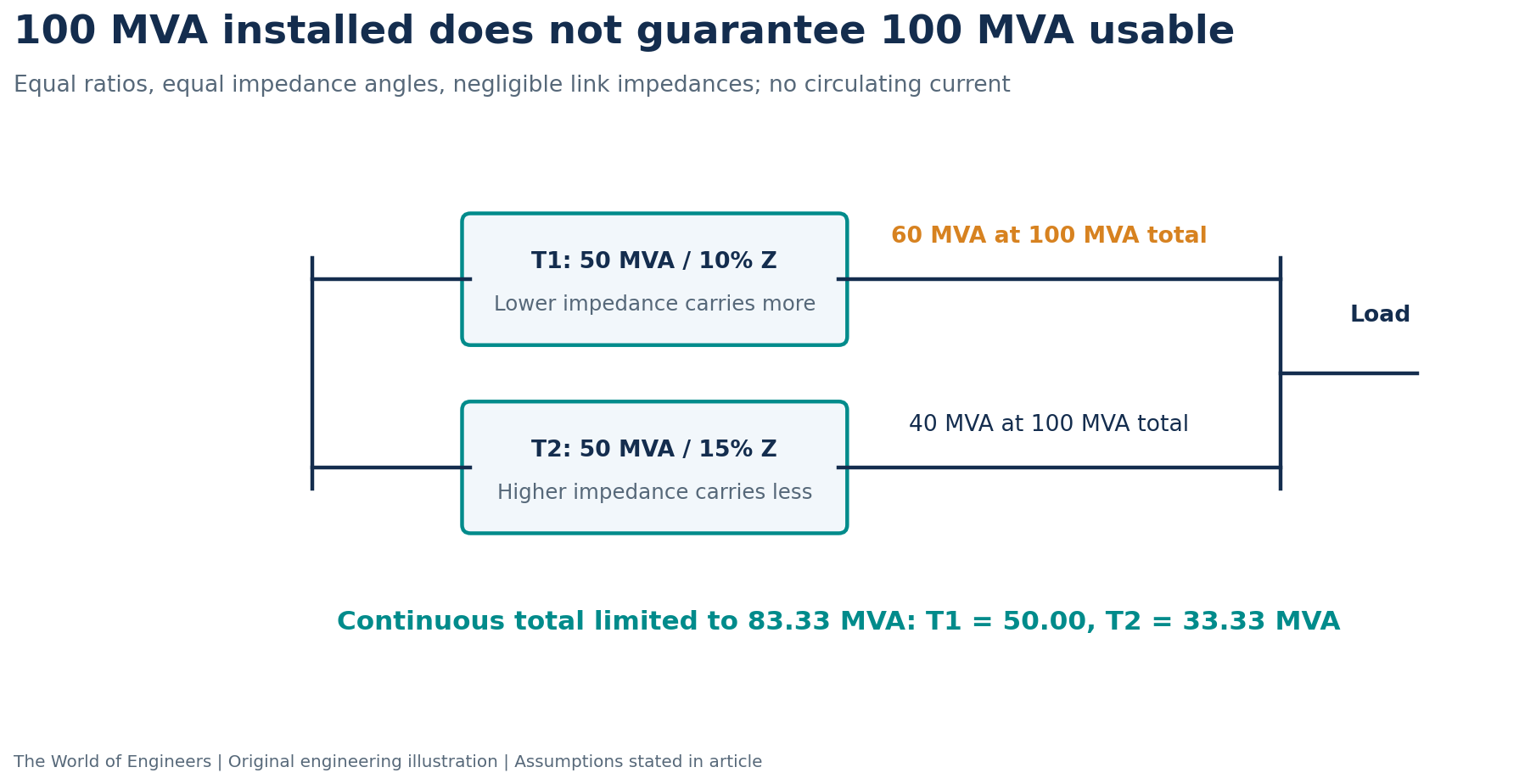
Schneider’s guidance identifies ratio, phase-angle relation and relative short-circuit impedance—including variation over the tapping range—as important compatibility conditions. It also illustrates the reduction of usable combined capacity when impedances differ. [4]
For unequal ratings, use a common base or work in referred ohms. An inverse split of the bare percentage numbers is wrong if their MVA bases differ. If X/R ratios differ, real and reactive load sharing need not follow one scalar percentage.
A useful small-mismatch estimate is Icirculating ≈ (E1−E2)/(Z1+Z2) on a consistent common base. For a 1% in-phase no-load voltage mismatch and a combined predominantly reactive 0.25 pu impedance, the magnitude is about 0.04 pu—roughly 84 A on the 13.8 kV, 50 MVA current base. Its phase and the load current determine the resulting individual loading.
Operating lesson: closing a bus coupler may add capacity, but it also changes fault duty, load sharing and protection zones. N−1 performance must be checked for the actual switching arrangement.
5. Motor starting: a transformer that limits faults can also limit acceleration
Motor starting imposes a large current demand on the source path. Schneider provides a useful screening relationship: voltage dip (%) ≈ (starting current / transformer rated current) × transformer impedance (%). Its guidance concerns LV transformer selection; the relationship is a screening aid, not a substitute for a detailed MV motor-starting study. [5]
For an illustrative starting demand equal to 0.60 times transformer rated current, the scalar estimates are 6%, 9% and 12% across 10%, 15% and 20% impedance. They exclude source and cable impedance, existing loads, motor starting power factor and the reduction of motor current with depressed voltage.
At a fixed slip, an induction motor’s electromagnetic torque is approximately proportional to terminal voltage squared when frequency and machine parameters are held fixed. A 0.90 pu voltage therefore suggests about 0.81 pu torque in that simplified comparison. Reduced torque can lengthen acceleration and increase thermal stress even if current falls.
Obtain the motor torque-speed and current-speed curves, driven-load torque, inertia, starting method and permitted starts. Check bus voltage, contactor/control ride-through, motor thermal limits and acceleration time together. A VFD or soft starter changes the problem; it does not justify ignoring it.
6. Reactive demand and losses: separate MVAR from MW
At current i pu, the series model absorbs approximately qseries = i²x pu and pseries = i²r pu. For the 15% voltage-case model at i = 1, x ≈ 0.14992 pu corresponds to 7.50 MVAR; r = 0.005 pu corresponds to 0.25 MW on the 50 MVA base. Magnetising demand and no-load losses are additional.
The MVAR term is reactive demand, not 7.50 MW of heating. Likewise, a 15% impedance nameplate is not an efficiency measurement. Compare guaranteed no-load loss, load loss at the reference temperature, auxiliary power and the actual loading profile separately.
Reactive compensation can improve voltage and reduce upstream current for a given useful load, but needs its own switching, overvoltage and harmonic assessment. Increasing source inductance can shift resonances with capacitor banks; a single impedance percentage does not identify the harmonic risk.
7. Three-winding transformers: ask for the complete impedance set
For a 380/132/13.8 kV transformer, one quoted impedance cannot describe every winding interaction. Obtain the H–M, H–L and M–L values, their bases, tap positions and reference conditions. Pairwise tests consider the remaining winding open; a loaded tertiary creates a different operating problem.
For a common-base positive-sequence star equivalent, the pairwise relationships are zHM = zH+zM, zHL = zH+zL and zML = zM+zL. Solving these simultaneous equations gives the branch values shown below. Use complex values consistently, or an explicitly justified reactance-only approximation.
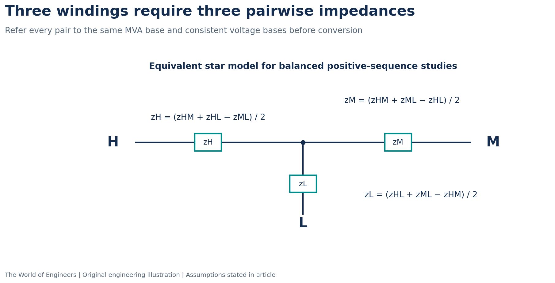
For an assumed common-base set xHM = 0.15, xHL = 0.25 and xML = 0.20 pu, the equivalent branches are xH = 0.10, xM = 0.05 and xL = 0.15 pu. Each pair adds back to its input value.
Some legitimate three-winding equivalents can produce a negative mathematical branch. Do not automatically replace it with zero; investigate the data and modelling convention with the OEM. Zero-sequence behaviour requires winding connections, neutral grounding and construction data rather than blindly copying this star.
Autotransformers require additional care because the windings share an electrical connection. See Autotransformers in EHV Power Systems: Theory, Maths & Practice.

8. Does higher impedance reduce the EPC price?
It may reduce some downstream duties, but there is no reliable universal relationship between transformer impedance and transformer purchase price. Leakage-field control, geometry, insulation, short-circuit forces, transport constraints and guaranteed losses interact within the manufacturer’s design.
IEC 60076-5 addresses thermal and dynamic withstand of external short circuits. A higher impedance does not by itself prove that the transformer satisfies its contractual withstand duty. [7]
| Package or decision | Possible influence of changing impedance | Commercial evidence needed |
|---|---|---|
| MV switchgear and busbars | Fault duty may change; the selected rating class may or may not change. | Approved maximum-fault study, future network cases and vendor prices. |
| Power transformer | Design and loss guarantees can change in either cost direction. | Comparable compliant quotations with the same scope and guarantees. |
| Motor feeders | Starting performance may require a revised starter, drive, cable or transformer arrangement. | Validated motor-starting study and equipment offers. |
| Parallel expansion | Mismatch can reduce usable capacity or complicate tap control. | Complex impedance data, load-sharing study and control scope. |
| Protection and CTs | Fault levels, through-fault conditions and coordination requirements change. | Protection/CT assessment, clearing-time requirements and testing scope. |
| Voltage support | Additional compensation or operating restrictions may be needed. | Load-flow results, harmonic/transient checks and compensation pricing. |
Evaluate the complete solution: transformer + switchgear + protection + starting equipment + compensation + losses + outages + future expansion. Avoid claiming a saving from a lower fault class before proving that the complete network remains below its rating.
The total earth-grid current cannot be inferred from the transformer three-phase fault table. It depends on earth-fault sequence networks, grounding, current division and fault duration. Nor can a lower transformer-fed RMS current alone justify a smaller cable or CT: thermal time, peak duty and other contributions remain relevant.
For a practical procurement workflow, read Substation Tendering & Contract Management.
9. Tolerances, taps and factory results: the values that move your study
A guaranteed nominal value and the factory-measured value need not be identical. Establish the permitted range from the applicable standard edition and the project-specific contract. Do not copy a generic tolerance into every two-winding, three-winding or tapped-transformer specification.
For sensitivity only, suppose a 15% nominal transformer could fall between 13.5% and 16.5%. This is an assumed ±10% relative range, not a statement of the applicable IEC tolerance. With the same 0.02 pu source, the screening current ranges from 13.50 kA at the low-impedance end to 11.31 kA at the high end. A nominal-only result of 12.30 kA hides that spread.
Request impedance at the required taps and loading bases, load losses at the reference temperature, and the measured R/X information required by the study. Use the guaranteed limiting values for design envelopes and the accepted measured values for the final as-built model.
Link the FAT result back to the approved design. If it lies outside a contractual guarantee or invalidates a study assumption, close the engineering and commercial consequences before acceptance. Our power transformer testing and commissioning guide explains the broader testing workflow.
10. A procurement checklist you can use
| Information to request | Why it matters |
|---|---|
| Rated power of each winding and every cooling stage | Defines the percentage and current bases. |
| Voltage ratio, vector group, frequency and tap range | Establishes connection compatibility and operating conditions. |
| Pairwise impedance, stated MVA base and tap position | Prevents incompatible comparisons and incomplete three-winding models. |
| Permitted tolerance and guaranteed minimum/maximum values | Defines worst-case fault, voltage and load-sharing envelopes. |
| R/X or suitable load-loss and impedance data at reference temperature | Supports complex-network, peak-duty and voltage calculations. |
| Zero-sequence data and neutral/tertiary arrangement | Required for earth faults and grounding studies. |
| Short-circuit thermal/dynamic withstand evidence | Separate from a statement of percent impedance. |
| Parallel-operation and OLTC compatibility statement | Addresses both normal sharing and circulating current. |
| Losses, auxiliary power and capability restrictions | Supports lifecycle comparison and operating limits. |
| FAT reports and approved final model | Makes the delivered equipment traceable to the studied design. |
11. Choose a feasible range, then compare compliant designs
Start with the operating configurations: normal bus split, coupler closed, transformer out, future expansion and credible source-strength extremes. Establish the maximum fault duty, minimum protection requirements, steady-state voltage limits and motor-starting criteria. Then test candidate impedances against all of them.
A useful first screening inequality is zT,min ≳ Ibase/Iallowed − zsource,min for the simple aligned-impedance, c = 1 case. It suggests the minimum impedance needed to respect a current ceiling. It is not an equipment selection rule; apply actual corrections, tolerances and additional infeed in the formal study.
Voltage performance and motor acceleration can impose an opposing upper constraint. If the lower and upper constraints do not overlap, change the wider design: bus arrangement, transformer rating, compensation, starting method or another justified network solution. Do not force a percentage to solve incompatible requirements.
Finally, compare OEM-supported alternatives inside the feasible range using guaranteed performance and complete EPC cost. A 20% transformer may solve a fault-duty problem and fail a starting requirement; a 10% transformer may improve voltage performance and exceed a bus fault limit. The engineering task is to demonstrate an acceptable combination.
Frequently asked technical questions
Is lower impedance always better?
No. It can improve voltage performance in a given inductive design but increases transformer-fed fault current. The useful value depends on the complete network and equipment limits.
Does a 15% transformer lose 15% of its power?
No. Impedance combines resistance and reactance. Efficiency requires active-loss data and a defined operating point.
Can two transformers be paralleled if their impedances differ?
Possibly, with verified compatibility and acceptable sharing. Different impedances can reduce usable combined capacity; ratio, phase displacement, X/R and link impedances must also be checked.
Does an OLTC eliminate high-impedance problems?
It can correct part of the steady-state voltage deviation within its limits. It does not remove the impedance, guarantee motor acceleration or establish acceptable protection performance.
Can transformer impedance be changed easily after delivery?
It is principally a winding-design characteristic. An external reactor changes the system impedance; it does not make the delivered transformer a different guaranteed design. Such a change requires new studies and approval.
Related articles from The World of Engineers
Transformer Cooling: ONAN, ONAF, OFAF and ODAF · Power Transformer Testing and Commissioning · Autotransformers in EHV Power Systems · Grid-Forming BESS vs Synchronous Condensers · Current Transformer Protection Units
Optional professional development — affiliate link
Sponsored / affiliate: for readers also developing cloud and digital skills, our existing Udemy partner link leads to an AWS certification exam-voucher offer. This is separate from the transformer topic; it is not a power-transformer course or an electrical-engineering certification.
View the Udemy-tracked AWS exam-voucher offer. Check the current destination, eligibility, availability and terms before purchase. We may earn a commission through this link; no discount amount or validity period is guaranteed here.
References and image credits
[1] Schneider Electric: Definition of short-circuit impedance of a pair of windings.
[2] Schneider Electric Electrical Installation Guide: Transformer-secondary short-circuit current.
[3] Schneider Electric Electrical Installation Guide: Combining upstream component impedances.
[4] Schneider Electric: Parallel transformers with different short-circuit impedances.
[5] Schneider Electric: Selecting a transformer to feed a motor.
[6] IEC 60076-1:2011 — Power transformers, General.
[7] IEC 60076-5:2006 — Ability to withstand short circuit.
[8] IEC 60909-0:2026 — Calculation of short-circuit currents.
[9] KEVOS: Windings, load loss and voltage regulation.
Source note: the IEC links identify the relevant publication scope and edition; this article does not reproduce paid standard clauses or claim a clause-by-clause compliance assessment. Distribution-transformer manufacturer examples are used for the underlying circuit principles, with the larger worked case and its limitations stated separately.
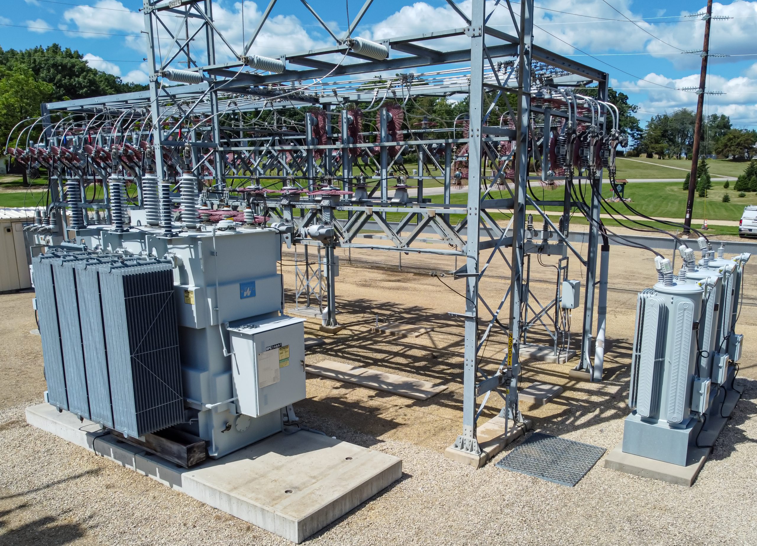
Photographs: Substation Power Transformer 1, Yoshieslunchbox, CC BY-SA 4.0; Transformer at substation, Wikideas1, CC0 1.0. Photographs do not identify the worked-example equipment. Cover: AI-generated editorial illustration. Diagrams and chart: original calculated illustrations.
Question for your next design review: was the transformer impedance selected from a coordinated network study, or carried forward from a previous project without testing the new operating conditions?