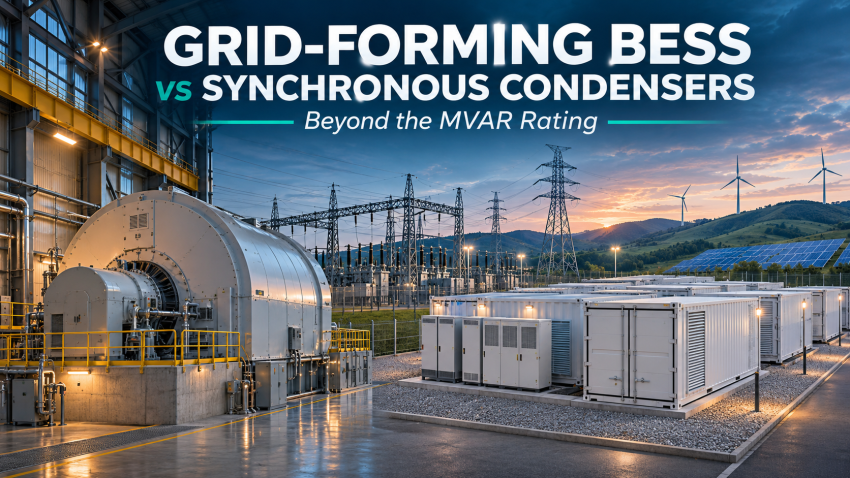
A battery and a rotating machine can carry similar reactive-power ratings while behaving very differently during the disturbance that matters most. Can a grid-forming battery energy storage system replace a synchronous condenser? Sometimes—but only after the required services, operating envelope and evidence of compliance have been defined.
This technical investigation compares the two technologies through fault response, voltage support, inertia, energy limits, protection, lifecycle cost and EPC procurement. It includes original illustrative calculations, rather than claiming to present a new network simulation.
Research basis: primary publications from ENTSO-E, AEMO, Powerlink/ARENA and U.S. national-laboratory research. Reviewed 9 November 2026. Published findings are cited inline. All numerical examples below are explicitly assumed, are not OEM guarantees and do not represent an SEC/National Grid SA project.
Navigate: The grid problem · Technical comparison · Worked calculations · Research evidence · Study programme · Lifecycle cost · Tender checklist · Decision framework
1. Define what is being replaced
A synchronous condenser is an excited synchronous machine operated without a prime mover delivering sustained shaft power. Its useful services include adjustable reactive power, physical rotational inertia and short-circuit contribution. It draws active power to cover losses; a flywheel can increase stored kinetic energy. These services are related, but are not interchangeable. [1]
A grid-forming BESS combines a battery, DC system, power conversion system, transformers and controls. GFM controls establish an internal voltage reference and respond to network disturbances within their capability envelope. Merely adding fast frequency response to a grid-following battery does not establish grid-forming behaviour. The useful distinction is the terminal response, not a product label. [2]
| Problem | What must be demonstrated |
|---|---|
| Insufficient dynamic voltage support | Reactive capability and acceptable voltage recovery at the specified connection point. |
| Weak-grid converter interaction | Stable operation and adequate damping across credible network and control conditions. |
| Insufficient frequency support | Required active-power response, duration, reserve and recovery behaviour. |
| Insufficient protection performance | Fault waveforms that allow the installed protection to detect and selectively clear faults. |
| Restoration requirement | A separately engineered black-start/islanding sequence, including auxiliaries and transformer energisation. |
Engineering implication: a proposal may solve a voltage-control problem while leaving a protection problem unresolved. A single equipment rating cannot close both questions.
2. Compare the physical response, not only the nameplate
| Requirement | Synchronous condenser | Grid-forming BESS |
|---|---|---|
| Reactive support | Excitation-controlled; constrained by stator/rotor heating and the machine capability curve. | Converter-controlled; constrained by current, voltage, temperature and concurrent active power. |
| Fault response | Machine electromagnetic response through subtransient/transient impedances; current evolves with time. | Control- and hardware-dependent; current limitation changes the response during severe faults. |
| Inertia/frequency | Kinetic energy exchanged as rotor speed changes; no sustained prime-mover energy supply. | Controlled active-power exchange from the DC energy source, subject to headroom and energy availability. |
| Weak-grid stability | May strengthen local voltage behaviour; effectiveness depends on location and network. | May stabilise converter-rich networks; effectiveness depends on location, controls and limits. |
| Sustained MW support | No sustained net generation; losses must be supplied. | Can discharge for the usable energy duration and recharge when permitted. |
| Protection compatibility | Existing schemes often assume synchronous-source behaviour; still requires coordination. | Sequence content, phase angle and current-limiting behaviour need explicit assessment. |
| Availability | Machine, excitation, cooling, starting and auxiliary systems matter. | Battery, PCS, cooling, BMS, controls, auxiliaries and service reservations matter. |
| Black start | Cannot energise a dead network independently without an external energy source and starting arrangement. | Possible only if the complete plant and operating sequence are designed and validated for it. |
This table is an engineering synthesis, not a universal product ranking. National-laboratory research identifies frequency control, voltage control, protection, fault ride-through and modelling as distinct areas of GFM assessment. [8]
3. The fault-current question that MVAR comparisons miss
For a simplified synchronous source behind predominantly inductive impedance, initial symmetrical fault current can be screened using I″ ≈ E″/X″ in per unit. The actual calculation must include the transformer, network, pre-fault voltage, machine parameters, sequence networks and relevant time constants. A machine-terminal result is not automatically its contribution at the high-voltage connection point.
For a converter, the unconstrained voltage-source response can demand more current than its semiconductors permit. The current-limiting strategy then becomes central to stability and fault recovery. It is unsafe to assume either an unlimited ideal voltage source or one universal fault-current multiplier for all GFM products. [3]
Protection also needs more than a magnitude. AEMO’s protection-quality fault-current trial explicitly examines duration, sequence composition and waveform properties alongside current amplitude. The existence of this work is evidence that protection equivalence must be demonstrated, not inferred from the GFM label. [4]
Ask how distance and directional elements behave for unbalanced faults, whether negative-sequence quantities remain usable, and how remote infeed changes apparent impedance. Transformer winding connections and neutral earthing determine zero-sequence paths; software cannot create a missing physical path. Differential protection also needs its own CT, communications and external-fault security assessment.
4. Worked calculations: four checks before any replacement claim
Illustrative assumptions only: a 380 kV connection point; a 100 MVA PCS; a 200 MWh battery; a 1.20 pu short-duration converter-current ceiling; and a 100 MVA synchronous-machine base. These deliberately round values are unrelated to a specific vendor or utility specification.
Check A — equal reactive support does not mean equal converter capacity
At nominal voltage, a simple apparent-power envelope gives P² + Q² ≤ S². A 100 MVA PCS exporting 80 MW has at most √(100² − 80²) = 60 MVAR of reactive capability within that idealised envelope.
If the same plant must deliver 80 MW and 86 MVAR simultaneously, the minimum geometric rating becomes √(80² + 86²) = 117.46 MVA. This is before voltage variation, losses, thermal derating, harmonics, overload restrictions or plant-level margins. The OEM P–Q–V capability envelope governs the design.
A specification that requests ±86 MVAR must also state whether that is at zero MW, at full active output, during charging, and at which voltage and measurement point. Do not assume symmetrical absorption and injection limits for either technology.
Check B — a current ceiling gives a useful bound, not a fault study
At 380 kV, the base current of a 100 MVA plant is Ibase = 100 / (√3 × 380) = 0.1519 kA. A 1.20 pu ceiling corresponds to 0.1823 kA on that base. Multiplying by nominal voltage yields a nominal-voltage current-equivalent of 120 MVA.
For contrast, assume E″ = 1 pu and combined machine-plus-transformer reactance X″ = 0.25 pu on the same base, with a three-phase terminal fault and resistance neglected. The initial screening result is 4 pu = 0.6077 kA, or a nominal-voltage equivalent of 400 MVA. That decaying synchronous response and the converter ceiling are different physical quantities, not a validated comparison of complete plants.
If a requirement explicitly calls for an incremental 3,000 MVA initial symmetrical contribution at 380 kV, its nominal-voltage current equivalent is 4.558 kA. Matching that amplitude using the assumed 1.20 pu ceiling alone would imply 3,000/1.20 = 2,500 MVA of converter base. This deliberately restrictive screening calculation is not a BESS sizing recommendation: it ignores waveform, duration, voltage collapse, network distribution and controls. It shows why the wording of the fault requirement matters.
Confirm whether 3,000 MVA means total bus fault level or additional plant contribution. Do not add source MVA values arithmetically without a network solution, and do not equate nominal-voltage current-equivalent MVA with power delivered into a collapsed-voltage fault.
Check C — voltage dips shrink the available power envelope
For a balanced converter at a current ceiling, the approximate apparent-power envelope scales as Savailable,pu ≤ Vpu × Imax,pu. At 0.50 pu terminal voltage and a 1.20 pu current ceiling, the upper envelope is 0.60 pu, or 60 MVA on a 100 MVA base. Unbalanced faults need phase-by-phase assessment.
There is no universal rule that every GFM unit should prioritise reactive current during a fault. ENTSO-E’s 2025 Phase II guidance describes proportional scaling of the unconstrained current vector and rejects independent active/reactive priority for its specified GFM response. That document is non-binding European guidance, not a Saudi requirement. Verify the applicable connection agreement and the OEM’s implemented behaviour. [7]
Check D — inertia, power headroom and energy are different constraints
For a hypothetical 100 MVA rotating machine with inertia constant H = 4 s, stored kinetic energy at rated speed is H × S = 400 MW·s = 0.111 MWh. That is total kinetic energy at rated speed, not energy fully available for extraction while maintaining synchronism.
Using the idealised inertia relation ΔP ≈ −(2HS/f₀)(df/dt), at 60 Hz and a frequency decline of 0.5 Hz/s the initial response is about 6.67 MW. This neglects damping and other dynamics; an actual network response requires dynamic analysis.
A separate battery service of 50 MW for 10 seconds needs 0.139 MWh at the AC terminals before losses. The energy looks small relative to 200 MWh, yet a 100 MW battery already exporting its full permitted output may have no upward reserve. At 80 MW output, only 20 MW of continuous upward headroom exists if 100 MW is the firm limit.
Specify both upward and downward reserve. Low state of charge can restrict discharge; high state of charge can restrict absorption. Include battery power limits, DC voltage, temperature, end-of-life condition and the recovery/recharge policy. A large MWh number does not guarantee an available fast MW response.
5. What published research actually demonstrates
Powerlink’s ARENA-supported study used detailed PSCAD models to investigate grid-forming batteries in a weak-grid setting. Only one supplier model was taken into detailed analysis, so the findings cannot be applied automatically to every GFM product. The report also examines coordination between the battery and renewable plants. [5]
ARENA’s project summary reports that a 100 MW battery supported connection of 300 MW of inverter-based generation in the studied case. This is a case result, not a universal 1:3 sizing rule and not proof of identical fault contribution to a condenser. [6]
ENTSO-E’s Phase II report adds a useful procurement lesson: define observable performance at the terminals, including behaviour near capability limits, rather than accepting a control-mode name alone. It provides technical guidance; it does not establish automatic local approval. [7]
Our engineering inference: replacement is plausible when the dominant need is demonstrable dynamic voltage stability and sufficient protection performance is already available or can be engineered. Where substantial specified fault contribution remains essential, a condenser, another fault-current source or a validated protection redesign may still be needed. Neither conclusion can be drawn from MVAR alone.
6. A project case: compare three complete options
Consider an illustrative 300 MW renewable cluster connected through a 380 kV substation. Following an outage, the remaining network has weaker voltage behaviour. Assume the owner also requires reactive support, frequency reserve and selective fault clearing. No EMT simulations have been performed for this article; the following is an evaluation plan, not a predicted result.
| Option | Potential role | What remains to be proven |
|---|---|---|
| Synchronous condenser | Reactive support, physical inertia and fault contribution. | Required MW reserve needs another source; verify damping, excitation, outages and fault-level limits. |
| Grid-forming BESS | Voltage-forming support, controlled frequency response and energy services. | Verify current-limited stability, relay performance, reserved headroom, SOC and end-of-life capability. |
| Condenser plus GFM BESS | Allocate fault/inertia duties and active-energy services across complementary assets. | Optimise both ratings; validate interactions, common auxiliaries, dispatch and failure cases. |
Do not assume the hybrid requires the full original condenser rating plus a full standalone BESS. Optimisation may change both sizes, but any reduction needs studies. Two technologies on one site do not guarantee independent redundancy if they share a transformer, bus section, cooling dependency or control system.
7. The study programme that makes a conclusion defensible
| Assessment | Cases and evidence to require |
|---|---|
| Load flow and capability | Voltage range; maximum charging/discharging; zero MW; reactive demand; tap settings; losses; seasonal derating. |
| Short circuit and equipment duty | Minimum and maximum network strength; balanced/unbalanced faults; time-dependent contribution; breaker/CT/earthing duties. |
| RMS dynamic studies | Frequency events, reserve delivery, longer-duration recovery and system-wide electromechanical behaviour. |
| EMT studies | Faults, clearing times, phase jumps, current limitation, loss of network elements, weak/strong networks and neighbouring converter interactions. |
| Protection validation | Actual relay functions/settings; sequence response; remote infeed; communications loss; backup clearing and external-fault security. |
| Model and control validation | Version-controlled OEM models matching delivered firmware; parameter traceability; controller or hardware-in-the-loop testing where needed. |
| Commissioning and operation | Approved safe tests; disturbance recording; verified reserve/SOC policy; availability monitoring; change-control triggers. |
The test matrix should cross operating conditions rather than check them individually. A successful zero-MW test does not prove fault recovery at maximum discharge, low SOC, high ambient temperature and N−1 network conditions. Include post-fault recovery, repeated disturbances and time spent at current or energy limits.
Define numerical acceptance criteria before studies begin: voltage recovery envelope, allowed oscillation damping, response delay, MW/MVAR duration, frequency limits, relay operation and plant availability. Agree them with the relevant system operator; avoid importing another jurisdiction’s thresholds without approval.
8. Lifecycle cost: compare a guaranteed service package
A comparison in SAR/MVAR hides major differences in delivered services. Use an equal evaluation period, connection boundary, availability target and set of technical obligations. A battery’s MW, MWh and MVA ratings price different capabilities.
Present-value framework: PV cost = initial EPC cost + Σ[(O&M + losses + replacements + augmentation + service-related costs − eligible net revenues)t / (1+r)t] − discounted residual value. Keep financing, tax and inflation assumptions consistent and avoid counting the same energy cost twice.
| Cost item | Condenser evaluation | BESS evaluation |
|---|---|---|
| Initial EPC | Machine, excitation, starting system, civil works, cooling, transformer and connection. | Battery, PCS, BMS/EMS, HVAC, fire provisions, transformer and connection. |
| Operating losses | Machine/excitation losses and auxiliaries across duty points. | Standby/PCS/HVAC losses plus cycling losses under the actual dispatch profile. |
| Long-term work | Planned outages, rotating equipment maintenance and control/auxiliary renewal. | Calendar/cycle degradation, augmentation, battery replacement and PCS/control renewal. |
| Reserved capability | Availability and any operating restrictions on the contracted service. | Opportunity cost of MW headroom and SOC reservations, without assuming unrestricted revenue stacking. |
| Risk and end of life | Availability guarantees, spares, decommissioning and residual value. | Warranty throughput, guaranteed end-of-life duty, recycling/decommissioning and residual value. |
The U.S. DOE cost assessment explicitly models storage degradation, augmentation and replacement. Its framework is useful; its historical cost inputs should not be treated as current Saudi quotations. Obtain comparable vendor guarantees and local EPC pricing. [9]
Original cost sensitivity: an assumed continuous auxiliary-loss difference of 0.5 MW equals 4,380 MWh per year at 8,760 hours. At an assumed internal energy value of SAR 200/MWh, that is SAR 876,000/year. Over 20 years at an 8% real discount rate, with constant annual operation and no escalation, the present value is about SAR 8.60 million. This is not a claim about either technology’s typical losses; it shows why guaranteed loss curves matter.
9. What an EPC tender should ask the supplier
| Tender requirement | Required response |
|---|---|
| Guaranteed measurement boundary | State machine/PCS terminals or HV point of connection; include transformer and collector-system effects. |
| Simultaneous duties | Provide guaranteed P–Q–V capability at required temperatures, SOC ranges, charging/discharging points and end-of-life conditions. |
| Fault contribution | Provide RMS/peak current versus time, sequence content, limiting logic, repeated-fault capability and validated models. |
| Frequency service | Specify response shape, delay, power, duration, energy/headroom reservation, recovery and performance while current-limited. |
| Grid-forming behaviour | Define measurable voltage-source behaviour, fault recovery and synchronisation requirements; identify firmware and configurable parameters. |
| Operating envelope | Declare unavailable modes, blocked conditions, minimum SOC, auxiliary dependencies and maintenance restrictions. |
| Study responsibility | Identify who supplies confidential models, runs network/EMT studies, resolves adverse interactions and implements approved tuning. |
| Acceptance and guarantees | Agree model validation, factory/site tests, performance remedies and the treatment of firmware or plant changes. |
| Scope interfaces | Allocate starting/black-start systems, protection, telecom, fire systems, cooling, auxiliary power and connection works explicitly. |
For a Saudi tender, read the actual utility requirements, employer’s specification and approved responsibility matrix. International research supports evaluation; it does not authorise substituting equipment prescribed by the contract. Keep any alternative as a documented, technically supported proposal until accepted.
10. When does replacement make sense?
| Project condition | Engineering decision |
|---|---|
| Main need is voltage stability/damping; adequate fault and protection performance can be demonstrated. | GFM BESS is a credible candidate, subject to validated plant/network studies and guaranteed availability. |
| Specification requires substantial incremental short-circuit contribution with defined duration/sequence behaviour. | Do not accept BESS equivalence from MVAR or GFM status. Prove the exact requirement or retain another compliant source. |
| Both sustained active-power reserve and fault/inertia services are needed. | Evaluate a hybrid and compare complete service packages. |
| Existing switchgear is near its fault-duty limit. | Assess maximum duty as well as minimum strength; added synchronous contribution may create another constraint. |
| OEM model, actual firmware or low-SOC capability is unverified. | Keep compliance pending; a favourable generic simulation does not close the item. |
Answer: grid-forming batteries can replace selected functions of synchronous condensers in suitable, demonstrated applications. Full replacement requires evidence that every contracted service survives the specified disturbances and operating conditions. The procurement decision belongs at the level of network performance, protection and lifecycle guarantees.
For the next design review: which requirement is actually driving your condenser—reactive support, damping, inertia, fault current or a combination? The answer determines what a credible alternative must prove.
Related technical reading
Energy Storage Technologies in Detail · Circuit Breaker vs Isolator vs Earthing Switch · Transformer Cooling and Multiple MVA Ratings
References and research notes
[1] ENTSO-E, Synchronous Condensers (25 March 2025).
[2] Introduction to Grid Forming Inverters (2023), NREL/PR-5D00-90256.
[4] AEMO, Grid-Forming Inverter Protection-Quality Fault Current Trial.
[5] Powerlink, PSCAD Assessment of the Effectiveness of Grid Forming Batteries (April 2021).
[6] ARENA, Powerlink Cost-Effective System Strength Study.
[7] ENTSO-E, Grid Forming Capability of Power Park Modules, Phase II (2025), especially pp. 30–34.
[8] Lin et al., Research Roadmap on Grid-Forming Inverters (2020), NREL/TP-5D00-73476.
[9] U.S. DOE, Grid Energy Storage Technology Cost and Performance Assessment (2022).
Method note: this article is an independent technical synthesis with original illustrative arithmetic. It does not claim a new EMT study, equipment certification, universal sizing ratio or utility endorsement. Source findings are separated from assumed examples so that readers can audit the argument.