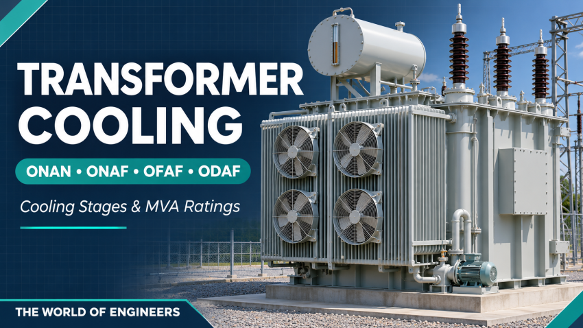
Why does one transformer have three ratings, such as 300/400/500 MVA? The ratings can describe the capacity of the same transformer under different cooling conditions. The voltage ratio stays the same; the available cooling changes.
Transformer cooling codes explain how the insulating liquid moves inside the transformer and how heat leaves the cooling equipment. This guide covers ONAN, ONAF, OFAF and ODAF, including two-stage fan cooling and practical nameplate examples.
For the equipment itself, read Main Components of Substation—Power Transformers and our Autotransformers in EHV Power Systems guide.
1. What do the four cooling-code letters mean?
Read the four positions separately. The first two identify the internal cooling medium and its circulation. The last two identify the external cooling medium and its circulation. IEC 60076-2 identifies cooling methods and covers temperature-rise requirements and tests.
| Position | Meaning | Codes relevant to this guide |
|---|---|---|
| First letter | Internal cooling medium in contact with the windings. | O: mineral oil or synthetic insulating liquid with fire point at or below 300°C. Other liquids can require different letters. |
| Second letter | Internal circulation arrangement. | N: natural circulation. F: forced, non-directed circulation. D: forced circulation directed into at least the main windings. |
| Third letter | External cooling medium. | A: air. W: water. |
| Fourth letter | External circulation arrangement. | N: natural convection. F: forced circulation, using fans for air cooling. |
These letters describe a cooling arrangement. They do not state the number of radiators, fan motors, pumps or standby units.
2. ONAN vs ONAF vs OFAF vs ODAF
| Code | Internal oil circulation | External air circulation | Main cooling equipment |
|---|---|---|---|
| ONAN | Natural convection. | Natural convection. | Tank cooling surfaces and/or radiators; no oil-circulation pumps or cooling fans required for this mode. |
| ONAF | Natural convection. | Fans force air over cooling surfaces. | Radiators/cooling banks and fans. |
| OFAF | Pumps circulate oil through the cooling equipment without the OD directed-flow arrangement. | Fans force air over cooling surfaces. | Oil pumps, fans and suitable heat exchangers/cooling banks. |
| ODAF | Pumped oil is directed into at least the main windings. | Fans force air over cooling surfaces. | Oil pumps, fans, heat exchangers and an internal directed-flow design. |
The IEEE-hosted transformer specification presentation distinguishes OFAF’s non-directed flow from ODAF’s directed flow. Siemens Energy’s power transformer brochure also describes oil-air cooling arrangements and attached or separate cooler banks.
ONAN: natural oil and natural air
Heat moves from the active part into the oil. The warmer oil rises and transfers heat through the cooling surfaces. Cooler oil returns through the natural circulation path. No fan or pump power is required for the ONAN cooling mode itself, although controls, heaters and other transformer auxiliaries may still need a supply.
ONAF: natural oil with forced air
Fans improve heat transfer on the air side. The oil circulation remains natural. This distinction matters when preparing auxiliary-load schedules: a transformer with ONAF cooling should not automatically receive an allowance for oil-circulation pumps.
OFAF vs ODAF: what changes inside?
Both use forced oil and forced air. The difference is the internal oil-flow arrangement. In OFAF, pumped oil returns to the tank without the specified directed path into the main windings. In ODAF, the design directs the cooling flow into those windings.
ODAF is not simply OFAF with a larger pump. The winding ducts and internal hydraulic design matter. Retrofitting fans or pumps does not establish a new approved rating without engineering verification.
3. Understanding ONAN/ONAF1/ONAF2
ONAF1 and ONAF2 commonly identify two forced-air stages in project documents or OEM schedules. Both stages retain the ONAF cooling principle. The numerals identify stages; they do not create new four-letter cooling classes.
The US Bureau of Reclamation transformer guide describes multiple load ratings associated with cooling steps. Confirm the rating-to-stage mapping on the specific nameplate and approved cooling schedule.
| Illustrative stage | Equipment in service | Example rated capacity |
|---|---|---|
| ONAN | Natural cooling; no forced-air stage required. | 300 MVA |
| ONAF1 | The fan group or groups assigned to the first forced-air stage. | 400 MVA |
| ONAF2 | The additional fan group or groups required for the second forced-air stage. | 500 MVA |
Illustrative example only: these values and group assignments are not a universal standard or a confirmed rating for a particular project. ONAF2 does not necessarily mean exactly two fans, two banks or double the airflow. Fan quantities, redundancy and duty/standby logic follow the OEM design.
A third MVA rating does not prove that the transformer has oil pumps. Read the cooling codes beside the ratings.
4. How to read a 300/400/500 MVA nameplate
Suppose the approved nameplate explicitly pairs 300/400/500 MVA with ONAN/ONAF1/ONAF2. Read the entries in the stated order:
- 300 MVA is the rating assigned to ONAN operation.
- 400 MVA is the rating assigned to the first ONAF stage.
- 500 MVA is the rating assigned to the second ONAF stage.
These are alternative ratings of one transformer. Do not add them to obtain 1,200 MVA. Do not treat 500 MVA as the ONAN rating. Also check the specified ambient conditions, winding ratings, tapping requirements and temperature-rise basis.
If another nameplate pairs the same numerical ratings with ONAN/ONAF/OFAF, the highest stage includes forced-oil circulation. The numbers alone cannot distinguish that transformer from the two-stage ONAF example.
Multiple cooling ratings vs multiple winding ratings
A three-winding transformer can have separate ratings for its HV, intermediate-voltage and tertiary windings, as well as different cooling-stage ratings. A slash-separated number without its table headings is ambiguous. Read the full nameplate, guaranteed particulars and winding-loading restrictions.
For a 380/132/13.8 kV autotransformer, do not assume that the tertiary can supply the main transformer’s full MVA rating. Confirm the tertiary rating and permitted simultaneous loading with the OEM.
MVA is not MW
For a balanced AC load, active power is approximately MW = MVA × power factor. At 0.90 power factor, 500 MVA corresponds to 450 MW. The transformer’s current and thermal limits still apply; this arithmetic does not authorize additional loading.
5. How cooling stages start and stop
Cooling controls may use oil temperature, a winding-temperature indication or model, load information and other OEM-defined inputs. Modern monitoring can manage fan operation using measured and modeled conditions; Hitachi Energy’s monitoring overview describes this capability.
- A stage-start command should produce the required fan/pump operation and feedback.
- Separate start and stop thresholds can prevent repeated rapid cycling.
- Duty rotation, standby selection and automatic changeover are design-specific.
- Local/manual operation, remote indications and failure alarms require functional checks.
Do not copy temperature setpoints from another transformer. The approved control schematic and OEM setting schedule determine staging, alarms and trips.
6. What happens when fans or pumps fail?
Loss of a required cooling stage can reduce loading capability. The appropriate response depends on the failed equipment, redundancy, existing load, thermal condition and OEM instructions. Hitachi Energy’s cooling-service guidance explains the importance of cooling-system condition to transformer availability and life.
Do not assume that any fan failure immediately changes a 500 MVA unit to exactly 400 MVA. A standby unit may preserve a rated stage, or partial loss may require another operating limit. A forced-oil transformer may also have restrictions that prevent assuming an ONAN fallback.
Temporary loading beyond a nameplate rating requires an approved assessment. IEC 60076-7 addresses ambient temperature, loading, operating temperatures and thermal ageing for mineral-oil-immersed transformers.
7. Cooling equipment and tender-review checklist
| Item | What to confirm |
|---|---|
| Radiators / cooler banks | Quantity, arrangement, supports, valves and installation scope. |
| Fans | Quantity per stage, motor ratings, rotation, guards and standby philosophy. |
| Oil pumps, where applicable | Quantity, duty/standby arrangement, flow indication and operating restrictions. |
| Control and power cabinets | Motor protection, contactors, local/manual controls and automatic staging. |
| Auxiliary supplies | Voltage, frequency, connected/running load, starting duty and required redundancy. |
| Temperature monitoring | Oil/winding indication, sensors and approved control/alarm/trip interfaces. |
| Station interfaces | SAS/SCADA status, alarms, remote controls and cabling boundaries. |
| Testing and documentation | Applicable temperature-rise evidence, functional checks, settings and manuals. |
For installation interfaces, see Power Transformer Installation Plan. For acceptance checks, see Power Transformer Testing and Commissioning Checklist.
8. Saudi Arabia: check the actual ambient design basis
High ambient temperature reduces the temperature difference available for air cooling. A nameplate rating established for one ambient basis cannot automatically be applied to another. Schneider Electric’s ambient-temperature guidance notes that higher ambient conditions can require a design specifically suited to the application.
For a Saudi substation tender, confirm the project’s maximum and average ambient requirements, altitude, cooler clearances, dust conditions and any specified loss-of-cooling duty. Obtain the OEM’s guaranteed ratings for that basis. Do not apply one assumed percentage derating to every transformer.
Frequently asked questions
Does ONAF require an oil pump?
No oil-circulation pump is required by the ONAF cooling principle. Its forced circulation is on the air side.
Are ONAF1 and ONAF2 different oil-circulation methods?
No. They normally identify two forced-air stages. Confirm the OEM’s stage definitions.
Is the highest cooling rating an overload rating?
Not when it is an assigned nameplate rating for that cooling mode and specified service conditions. Loading beyond the applicable rating is a separate assessment.
Can I increase the rating by adding fans?
Only an engineered and approved upgrade can establish a revised rating. Cooling surfaces, internal thermal behavior, current-carrying parts, insulation, bushings and tap-changer limitations all need consideration.
References
- IEC 60076-2 — Temperature rise and cooling identification
- IEC 60076-7 — Loading guide for mineral-oil-immersed transformers
- IEEE PES/IAS technical presentation — Preparation of Transformer Specifications
- US Bureau of Reclamation — Transformers: Basics, Maintenance, and Diagnostics
- Siemens Energy — Power transformer brochure
- Hitachi Energy — Cooling system overhaul and upgrades
- Hitachi Energy — Monitoring systems
- Schneider Electric — Transformer ambient temperature requirements