If you’ve ever read an SEC tender scope of work or a project schedule for a Bulk Supply Point (BSP), you’ll know the sequence looks deceptively simple on paper — engineering, civil, installation, testing, energization etc. In reality, the schedule that wins the tender & survives contact with the site are often two different documents.
This guide walks through the HV Substation construction sequence & focus on how a real HV substation actually gets built, from Notice to Proceed to handover. Based on how SEC EPC (Lump Sum Turnkey) projects particularly a 380/132/13.8kV BSPs are typically sequenced in the field.
Phase 1 – Mobilization & Engineering (Months 1–6)
This phase runs in parallel with everything that follows — it never really “closes” before Phase 2 begins.
Contract to Notice to Proceed
Bank guarantees are issued, advance payment is released (usually 10–20% of contract value), and the contractor submits a master schedule for SEC approval. The advance payment is what actually funds the earliest procurement — cash flow here matters more than people expect.
Mobilization
Temporary site office, laydown area, and workers’ accommodation go up. A site-specific HSE plan must be approved before any physical work starts — SEC is strict on this.
Surveys
Topographic survey confirms ground levels against tender assumptions — discrepancies here are a common source of variation orders. Geotechnical investigation (boreholes, bearing capacity, groundwater level) directly drives foundation design, especially for transformer plinths and the GIS building, which both carry heavy point loads.
Detailed engineering
Civil, electrical, and layout drawings go through SEC’s IFC (Issued for Construction) approval cycle. Each round typically takes 2–4 weeks, and drawings often go through 2–3 revisions — schedules that assume first-pass approval are usually optimistic.
Procurement kickoff
Purchase orders for power transformers and GIS go out immediately after NTP. These carry 12–18 month manufacturing lead times, so a one-month slip here pushes the entire completion date by a month, regardless of how fast everything else moves. Secondary equipment (protection relays, SAS/SCADA, batteries) is ordered with shorter 4–8 month lead times, but still needs to land in time for panel installation in Phase 4.
Below are our most popolar and related posts
- 380kV BSP Projects Winners in 2025 in Saudi Arabia
- List of Contractors who Won Major BSP Projects in 2024 in KSA
- List of Top Substation contractors in KSA
- List of Contractors who Won Major OHTL Projects in 2024 in KSA
- SEC invited Bids for Synchronous Condenser Plants Phase II
- Extra High Voltage EHV Substation Design
Civil Works (Months 4–14) Phase 2
- Site grading, drainage, perimeter wall and fencing
- Equipment foundations: transformer plinths (with oil containment pits), GIS building foundation, gantry and structure foundations
- Cable trenches and ducts
- Control building (LCC) construction — this has to finish early enough to allow panel installation later
- Internal roads and mandatory firewalls between transformer bays per SEC fire code
the detailed construction sequence of a typical 380/132/13.8kV BSP is given below
Scope of Work
considering we have 1 380kv, 8 dia GIS building, 2 nos. 132kv 12 bays GIS buildings, a control building including switchgear room, battery room, office, communication room, customer/ interface building, and area of approx 400 by 400 m . Here’s how it actually breaks down:
Site-Wide Works (Months 4–6, must lead everything else)
- Bulk earthworks and grading across the full 400m × 400m (16 ha) plot — cut/fill to achieve the design finished levels, which depend on your geotech and flood/drainage study. On a site this size, this alone can run 6–10 weeks with proper compaction testing (Proctor density checks) at each layer.
- Perimeter wall and security fencing — usually an early package since it secures the site for the rest of construction and is often a separate subcontract that doesn’t block other trades.
- Main stormwater drainage network — sized for the whole plot, sloped to a discharge point or attenuation pond. This needs to go in before the internal road network and building foundations, since trench crossings later are disruptive.
- Earthing (grounding) grid — this is the one item that’s easy to underestimate. A site this size needs a buried copper grid mesh across the entire switchyard and building footprints, installed and tested (ground resistance, step/touch potential) before any structural foundation pour above it. It’s typically installed in coordination with, not after, the general grading — get this sequencing wrong and you end up trenching through finished gravel later.
Foundations — four parallel fronts (Months 5–13)
380kV GIS building (8-bay/diameter)
GIS buildings carry heavy point loads from the SF6 bays. Additionally significant floor loading for maintenance cranes. Expect a reinforced concrete raft or piled foundation depending on your geotech bearing capacity. an 8-bay 380kV GIS hall is a large-span structure. So foundation design usually needs to accommodate future crane rail loads if internal maintenance gantries are specified. This is usually your longest-lead foundation because of the size. Also because SEC/consultant approval on GIS building structural drawings tends to go through the most revision cycles.
132kV GIS buildings ×2 (12 bays each)
Similar logic, smaller footprint per building than the 380kV hall but you’re running two of them. In this case decide early whether they’re built sequentially by the same crew (cheaper, slower). Or in parallel with two crews (faster, needs more supervision and concurrent concrete supply capacity). For a 10-month civil window, parallel is usually necessary.
Control building (multi-function)
This one has more internal complexity than the GIS halls even though it’s structurally simpler. Switchgear room, battery room, office, and communication room each have different floor loading, HVAC, and cable-entry requirements:
- Switchgear/LV room: raised floor or cable trench system for panel cabling
- Battery room: acid-resistant flooring, dedicated ventilation for hydrogen off-gassing, often a bunded floor
- Communication room: raised access floor for fiber/telecom racks, tighter environmental control
- Office areas: standard finishes, but often the last priority in the schedule since they don’t gate energization
Customer/interface building
A separate structure for revenue metering and the utility/customer handover point. Although smaller footprint, but its cable route back to the main control building and GIS buildings needs early coordination. Since it’s often the point where SEC’s own systems interface with the customer’s, and that boundary is usually contractually significant (defines where your scope ends).
Underground Infrastructure (Months 6–12, threading through everything above)
- Cable trench network connecting all four buildings — this is a major undertaking on a 400×400m site. It’s typically routed as main trunk trenches with branch trenches to each building, sized for control, power, and fiber cabling with future spare capacity. Get this designed and roughed in before internal road paving, or you’ll be cutting finished pavement later.
- Firewalls/fire barriers — required around GIS SF6 storage/handling areas per SEC fire code, plus around any outdoor transformer bays if you have external power transformers feeding the 132kV or 13.8kV side.
- Oil containment — if transformers are indoor within the GIS buildings this is simpler; if any are outdoor, you need bunded pits sized to the largest transformer’s oil volume.
Internal Roads and Finishing (Months 10–14)
- Access roads sized for heavy transformer transport (SPMT routes need wider turning radii than normal roads — check this against your transformer delivery plan now, not when the transformer arrives)
- Gravel surfacing of the switchyard areas (standard practice for step-potential safety and drainage)
- Final grading, landscaping/dust suppression where required
Sequencing Logic Specific to Your Layout
The critical dependency chain here is: earthing grid → GIS building foundations → GIS building structure → GIS equipment installation window opens. Since you have three separate GIS structures (1×380kV + 2×132kV), whichever one has the longest lead-time GIS equipment order should get foundation priority — check your procurement schedule and civil-sequence the buildings to match, not by convenience of crew mobilization.
The control building is usually not on the critical path for energization. Secondary systems installation can compress if needed. But the customer/interface building’s cable route often gets forgotten until late. It is worth locking in its trench routing early so it doesn’t become a scope surprise in month 11.
Structural & Electromechanical Installation (Months 10–20) Phase 3
Summarize Sequence
- Steel structure erection: gantries and busbar support structures
- GIS building fit-out and bay installation — highly sequenced, factory-supervised work
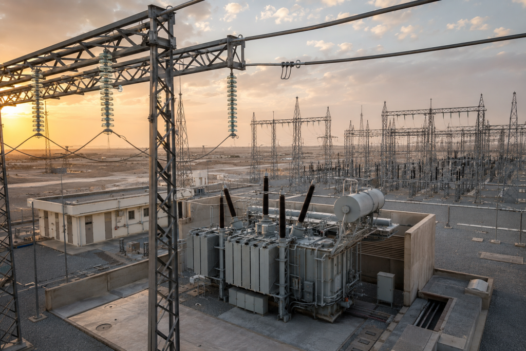
- Power transformer delivery and installation — a major logistics event involving SPMT transport, crane rigging, positioning, radiator and conservator fitting, bushing installation, and oil filling under vacuum
- Busbar and jumper connections, isolators, CTs/VTs, surge arresters
- Reactor and capacitor bank installation where specified
Detailed Sequence
With three separate GIS buildings running in parallel, this phase is really three coordinated installation programs sharing the same site logistics, crane resources, and commissioning window. Here’s how it plays out.
Sequencing Priority: Which GIS Building Goes First
Don’t default to “380kV first because it’s the biggest.” Sequence by whichever GIS equipment arrives from the factory first, since GIS installation is a factory-supervised, highly schedule-sensitive activity — once the manufacturer’s installation team and specialized tools are mobilized, you want the building ready and waiting, not the other way around. In practice:
- If your 380kV GIS has the longer manufacturing lead time (common, since 380kV bays are more complex). Its building foundation and structure should have been prioritized back in Phase 2, and it typically gets first installation slot here.
- The two 132kV GIS buildings (12 bays each) can often run installation in parallel with separate manufacturer commissioning teams if your contract and manufacturer capacity allow it. This is worth confirming early, since running them sequentially instead of in parallel can add 2-3 months.
380kV GIS Building — 8 Bays (Months 10–17)
- Building envelope completion — roof, cladding, and internal finishes must be weathertight before GIS installation starts. Since SF6 gas-insulated equipment installation requires a controlled, dust-free environment (GIS bays are assembled and gas-filled on site, and any contamination during assembly risks internal flashover later).
- Overhead crane/monorail commissioning inside the hall — GIS bay modules are heavy (often several tonnes per module) and need the building’s internal lifting equipment tested and certified before equipment offloading begins.
- Bay-by-bay assembly — busbar modules, circuit breaker modules, disconnector/earthing switch modules, and CT/VT modules are assembled per bay. Typically 2-4 weeks per bay depending on crew size and manufacturer supervision availability — across 8 bays this is usually run with 2 parallel assembly crews to compress duration
- SF6 gas filling and pressure testing per bay as assembly completes — this happens progressively, not all at once at the end.
- External connections — cable sealing ends or overhead bushings connecting the GIS to the outdoor gantry/busbar system, and connections down to the power transformers
132kV GIS Buildings ×2 — 12 Bays Each (Months 11–19)
Same assembly logic as above but at larger bay count per building. With two buildings, your critical decision is crew allocation:
- Parallel crews (recommended if achievable): two independent manufacturer teams work both buildings simultaneously — faster completion, but requires enough qualified GIS technicians (often a genuine constraint, since this is specialized labor, not general electrical crew)
- Sequential with crew transfer: one team finishes building A, moves to building B — cheaper on supervision cost, but adds real schedule length; only advisable if your overall timeline has slack
With 12 bays each, expect a longer in-building assembly duration than the 380kV hall even though voltage class is lower — bay count drives duration more than voltage class does at this stage.
Power Transformers — Delivery and Installation (Months 12–18, threading through both GIS programs)
- SPMT transport and offloading — this is the single highest-risk logistics event in the whole project. Confirm your Phase 2 access road design actually accommodates the transformer’s real transport dimensions and turning radius, not just the nameplate weight
- Positioning and rigging onto the foundation plinth
- Radiator, conservator, and bushing assembly (often shipped separately and fitted on site to keep transport dimensions manageable)
- Vacuum oil filling and degassing — a multi-day process requiring specialized equipment, done under strict environmental conditions (avoid this step during high-humidity periods if you have any schedule flexibility, since moisture ingress during oil filling is a known cause of later insulation issues)
- Bushing test and SFRA baseline test before energization eligibility
Given your voltage configuration, you likely have transformers stepping 380/132kV and 132/13.8kV — confirm each transformer’s delivery sequence against which GIS building needs to receive its connections first, since a transformer sitting on site without its downstream GIS ready to receive it is a real cost (demurrage-equivalent idle asset, security risk, and warranty clock considerations).
Outdoor Structural Works (Months 10–16, parallel to all of the above)
- Steel gantry and busbar support erection connecting the three GIS buildings to each other and to any outdoor equipment (surge arresters, outdoor CTs/VTs if not integrated into the GIS scope)
- Jumper and interconnection busbar installation between the 380kV GIS output and the 380/132kV transformer banks, and between 132kV GIS and the 132/13.8kV transformers
Coordination Risk Specific to Your Layout
The real project-management challenge with three GIS buildings isn’t any single building — it’s manufacturer resource contention. If all three GIS packages are from the same OEM (common, since utilities often prefer single-vendor GIS for spares/maintenance commonality), that vendor has a finite pool of qualified commissioning engineers globally. Lock in vendor resource allocation and mobilization dates contractually early in Phase 1 procurement — this is a more common real-world delay driver on multi-GIS-building projects than any civil or structural issue
Secondary Systems (Months 14–22, overlapping Phase 3) Phase 4
- Control, protection, metering, and communication panels installed in the LCC
- DC system (batteries, chargers) and AC auxiliary supply
- Substation Automation System (SAS) per IEC 61850, SCADA/RTU integration, and fiber/telecom links back to the National Control Center
- Cabling and termination between yard equipment and the control building
Testing & Commissioning (Months 20–24) Phase 5
- Pre-commissioning checks: insulation resistance, continuity, torque checks
- Individual equipment testing: transformer SFRA, ratio and winding resistance tests; CT/VT ratio and polarity checks; protection relay and scheme testing
- GIS SF6 gas filling with pressure and leak testing
- SAT (Site Acceptance Test) — an end-to-end functional test of protection, control, and SCADA
- Energization, usually staged: first from the 132kV or 380kV side per SEC’s switching instruction, then back-feeding the transformer, then progressively energizing downstream
Phase 6 – Handover
Punch list closure, as-built drawings, O&M manuals, and spare parts handover. The Defects Liability Period begins — typically 12 months — during which the contractor remains responsible for warranty repairs.
Three Things Worth Knowing From the Tendering Side
Transformer and GIS lead times drive the whole schedule. Everything else can usually be compressed to some degree. These two items can’t be. If a tender timeline looks aggressive, it’s worth checking whether it assumes transformer ordering starts against a letter of intent, ahead of formal NTP.
Energization is coordinated by SEC’s National Control Center, not the contractor. This is a hard external dependency that’s easy to underestimate when building a proposal schedule.
Civil delays cascade the hardest. If foundations aren’t ready when the transformer arrives on site, the contractor is paying demurrage and storage on one of the most expensive single items in the project.
Understanding this sequence matters on both sides of the table — for contractors building a realistic execution schedule, and for anyone reviewing or preparing a tender who needs to know which parts of a proposed timeline are genuinely compressible and which aren’t.