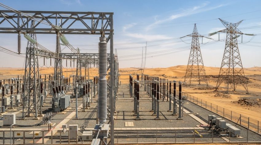
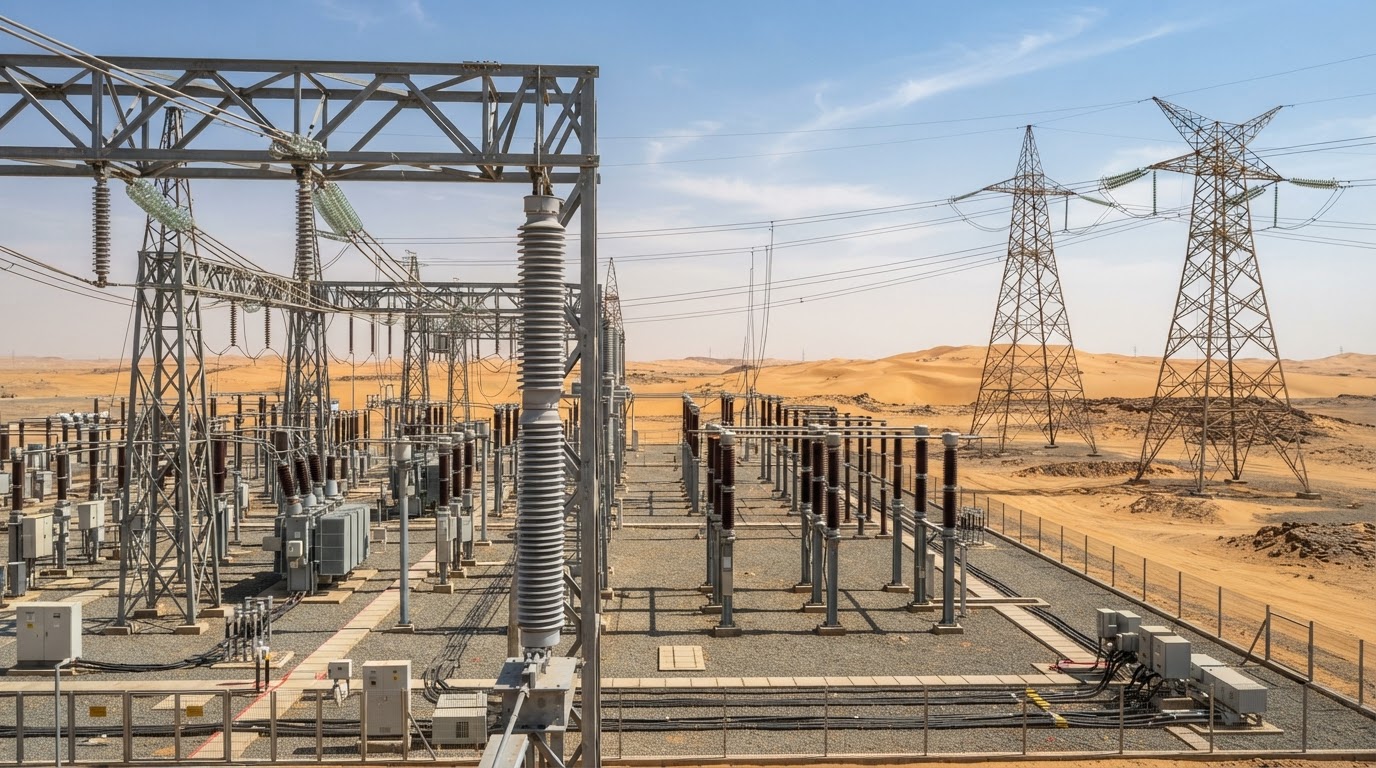
Electrical insulators provide both dielectric isolation and mechanical support in power networks. Correct selection requires coordinated evaluation of voltage withstand, surface pollution, mechanical loading, aging, fittings, installation geometry and manufacturer qualification. This engineering guide focuses on distribution, 132 kV, 220 kV and 380/400 kV transmission lines and AIS substations, including Saudi Arabian desert and coastal environments.
1. Functions and classification
An insulator prevents unwanted conduction between energized and grounded structures while carrying operational loads. Insulation is provided through bulk dielectric material and the external air/surface path. Its mechanical function may involve tension, compression, cantilever bending, torsion and combined loading.
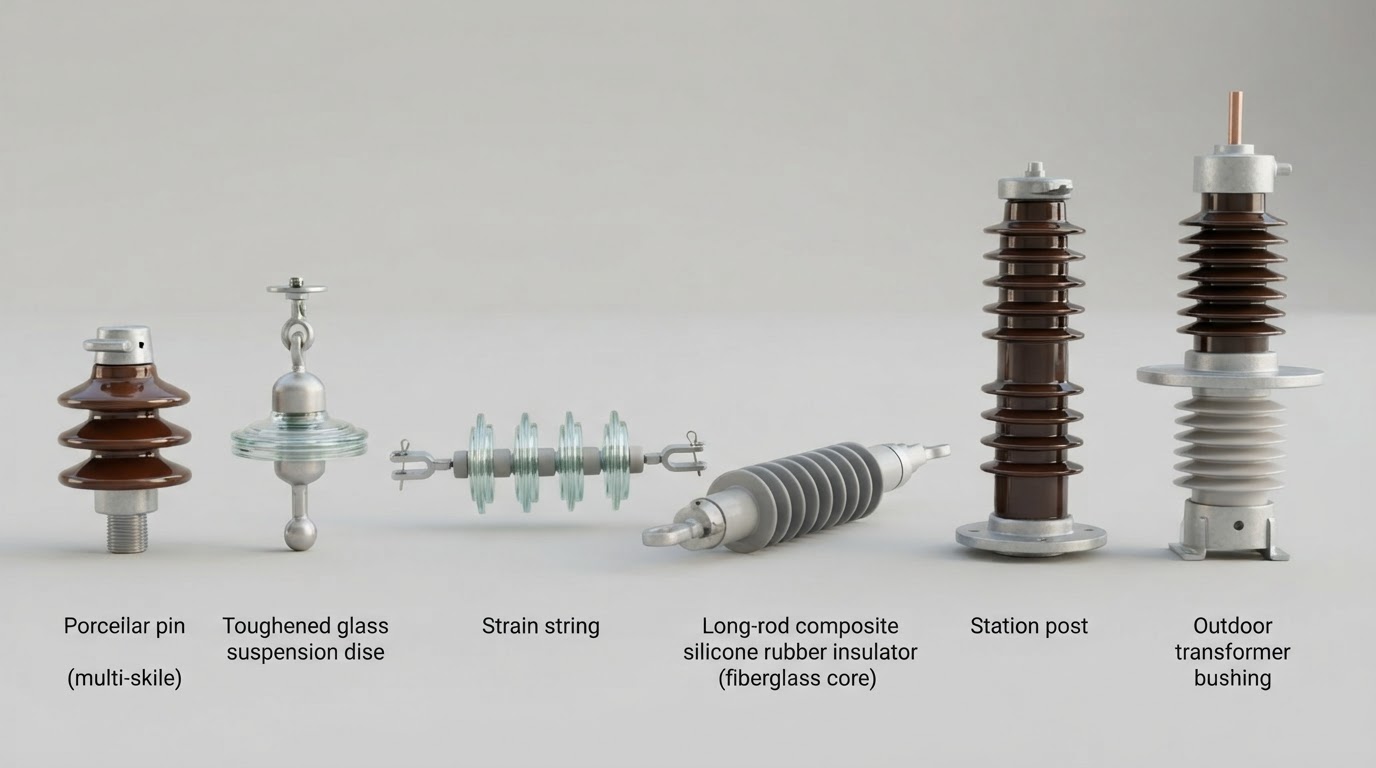
| Type | Construction and purpose | Main design concern |
|---|---|---|
| Pin / shackle | Distribution conductor support | Voltage class, bending and pollution |
| Cap-and-pin suspension | Series-connected glass or porcelain units on overhead lines | String length, creepage, mechanical failing load |
| Strain / dead-end | Horizontal or angled string transferring conductor tension | Longitudinal force and full hardware assembly |
| Composite long rod | FRP core, polymer sheds and metal end fittings | SML, seal integrity, aging, electric-field control |
| Station post | Rigid porcelain or composite equipment/busbar support | Cantilever and torsional strength |
| Line post / braced post | Conductor support attached to a tower or pole | Combined transverse and longitudinal forces |
| Bushing / hollow core | Conductor through grounded equipment enclosure | Internal dielectric and external insulation |
2. Materials: porcelain, toughened glass and polymer
| Characteristic | Porcelain | Toughened glass | Silicone composite |
|---|---|---|---|
| Insulating construction | Fired ceramic body | Tempered glass disc | FRP core with polymer housing |
| Weight | High | High | Relatively low |
| Surface wetting | Generally hydrophilic | Generally hydrophilic | Often hydrophobic when healthy |
| Failure visibility | Cracks may be subtle | Shattered disc often visible | Requires housing/interface inspection |
| Typical risks | Cracking, cement deterioration | Mechanical impact, damaged units | Tracking, erosion, sealing and core aging |
| Main uses | Station posts, discs, bushings | Transmission line discs | Line strings and posts |
Material selection is site-specific. Silicone rubber often performs favorably under pollution due to hydrophobicity and hydrophobicity transfer, but those characteristics may deteriorate with aging or discharge activity. Composite insulators also require careful electric-field grading and reliable end fitting seals.
3. Creepage distance versus dry arcing distance
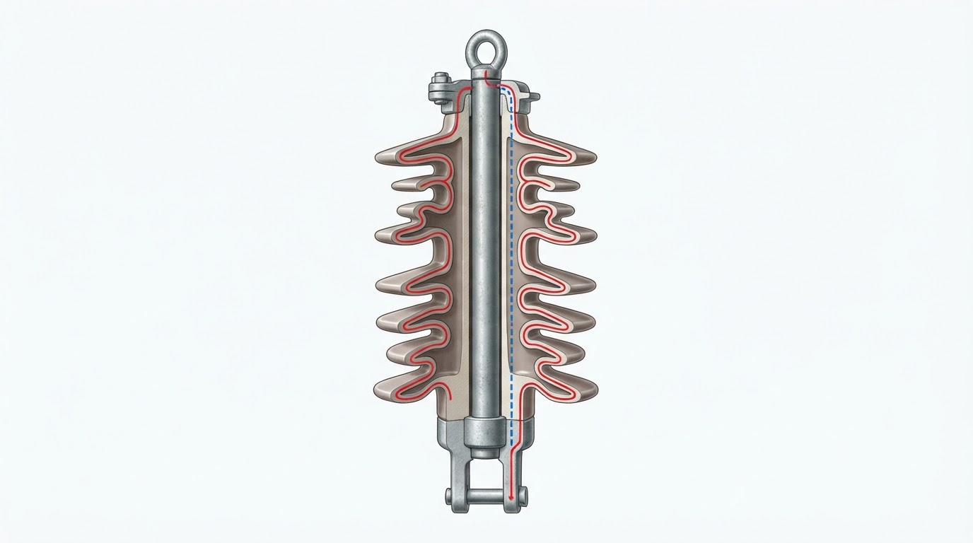
Creepage distance is the shortest path along the insulating surface between conductive parts. Dry arcing distance is the shortest external air path between electrodes. Additional sheds increase nominal creepage but do not necessarily increase dry arcing distance proportionately.
Unified specific creepage distance (USCD)
USCD = Lc / Uacross, where Lc is creepage in mm and Uacross is RMS voltage across the insulator in kV. For a phase-to-earth AC insulator, Uacross = Um / √3; therefore Lc = USCD × Um / √3. Here Um is the highest equipment voltage, not nominal line voltage.
Older specifications sometimes define SCD = Lc / Um based on line-to-line voltage. For a phase-to-earth insulator, USCD = √3 × SCD. 31 mm/kV traditional SCD corresponds to approximately 53.7 mm/kV USCD; the two quantities must not be interchanged.
Worked example: 380 kV network, Um = 420 kV
Assume a project-selected USCD of 53.7 mm/kV before candidate-specific adjustments. Lc = 53.7 × 420 / √3 = 13,021 mm. For a cap-and-pin disc offering 550 mm nominal creepage, preliminary count = ceiling(13,021 / 550) = 24 discs. If the disc spacing is 170 mm, nominal disc stack length is approximately 4,080 mm excluding fittings. This is only a creepage-based screening calculation, not a final string design or a universal IEC pollution-class requirement.
| Nominal system | Um | Illustrative creepage at USCD 53.7 mm/kV |
|---|---|---|
| 33 kV | 36 kV | 1,116 mm |
| 132 kV | 145 kV | 4,496 mm |
| 220 kV | 245 kV | 7,595 mm |
| 380/400 kV | 420 kV | 13,021 mm |
Interactive Creepage Distance Calculator
Calculate preliminary AC phase-to-earth insulator creepage requirements using IEC TS 60815 terminology. Select highest equipment voltage (Um), not merely nominal system voltage.
Minimum preliminary discs: 24
Nominal disc stack: 4,080 mm
Method: Lc = USCD × Um / √3; N = ceiling(Lc / creepage per disc). Example USCD 53.7 mm/kV is an illustrative project assumption, not a universal IEC requirement. This is a preliminary phase-to-earth AC screening tool, not final insulation coordination or string approval. Confirm pollution severity, altitude, impulse withstand, mechanical loads and utility specifications.
4. Pollution severity, ESDD, NSDD and flashover
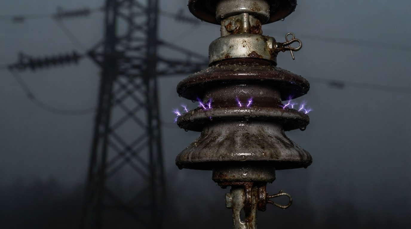
Dust, soluble salt and industrial deposits can accumulate on an insulator. Dew, fog or rain may wet the deposit, raising leakage current. Joule heating creates dry bands, followed by local arcs that can extend into a complete flashover.
ESDD (equivalent salt deposit density) characterizes soluble contamination; NSDD (non-soluble deposit density) characterizes insoluble deposits, normally in mg/cm². IEC TS 60815 selection requires site pollution assessment, a reference USCD and corrections for the candidate design. Geographic descriptions alone do not establish a reliable pollution class.
In Saudi Arabia, coastal salt, inland sand and industrial dust can occur separately or together. Long dry periods followed by humidity, fog or light rain can create particularly unfavorable surface conditions. Shed spacing, alternating profiles, self-cleaning behavior, material hydrophobicity, diameter and orientation all matter. More nominal creepage does not guarantee superior real-world pollution withstand.
5. Mechanical ratings in kN: SML, failing load and cantilever strength
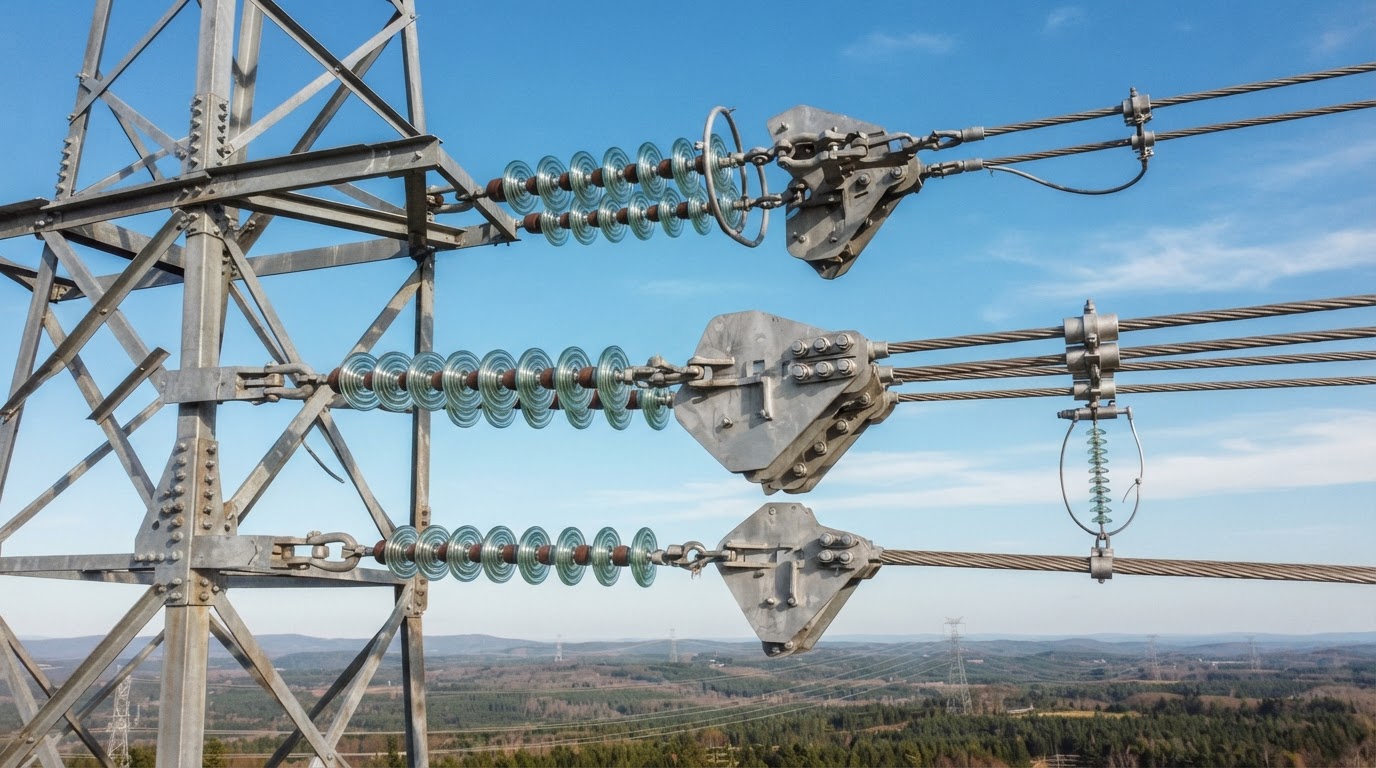
1 kN = 1,000 N, approximately 102 kgf of gravitational force. Mechanical rating is force, not mass. Common suspension/tension classes encountered in procurement include 70, 100, 120, 160, 210, 300 and 400 kN, depending on standard and manufacturer. These are not voltage classes: a 380 kV string is not automatically 160 or 210 kN.
| Term | Meaning / caution |
|---|---|
| SML | Specified mechanical load, especially for composite tension/suspension insulators; not continuous permissible service load |
| Mechanical failing load | Failure characteristic for relevant ceramic/glass units |
| RTL | Routine test load as specified by the applicable standard |
| Cantilever strength | Lateral force or associated bending moment for rigid posts |
| Torsional strength | Resistance to twisting, important for apparatus and support posts |
Illustrative tension-string calculation
Suppose the governing tensile load is 65 kN and the project explicitly requires a simplified factor of 2.5 relative to the selected rating. Required nominal rating ≥ 65 × 2.5 = 162.5 kN. A 160 kN unit would not meet that assumed criterion; a 210 kN class may be evaluated. The actual code/utility loading combinations, partial factors, load sharing and complete assembly capacity govern final selection. Do not universally apply a factor of 2.5.
Station post cantilever calculation
For an illustrative lateral force of 2.0 kN applied at 2.8 m, bending moment M = F × h = 5.6 kN·m. The supplier’s stated cantilever rating must be interpreted at its specified load application point and failure/working-load basis. Also evaluate busbar thermal movement, wind, seismic effects, short-circuit forces and combined loads.
6. Insulation coordination and voltage withstand
Creepage principally addresses polluted-surface performance; it does not establish lightning or switching impulse withstand. Assess power-frequency dry/wet withstand, lightning impulse withstand (LIWV), switching impulse withstand (SIWV), puncture withstand, corona/RIV and the external air clearances. For 420 kV-class equipment, standardized insulation levels may include LIWV values such as 1,425 or 1,550 kV and switching impulse withstand around 1,050 kV, depending on selected standard combinations and equipment. These are equipment-level examples, not automatic ratings of an individual string.
Altitude reduces external air insulation strength; apply the applicable insulation coordination correction. Increasing creepage alone is not an adequate altitude correction.
7. Voltage distribution, grading rings and corona
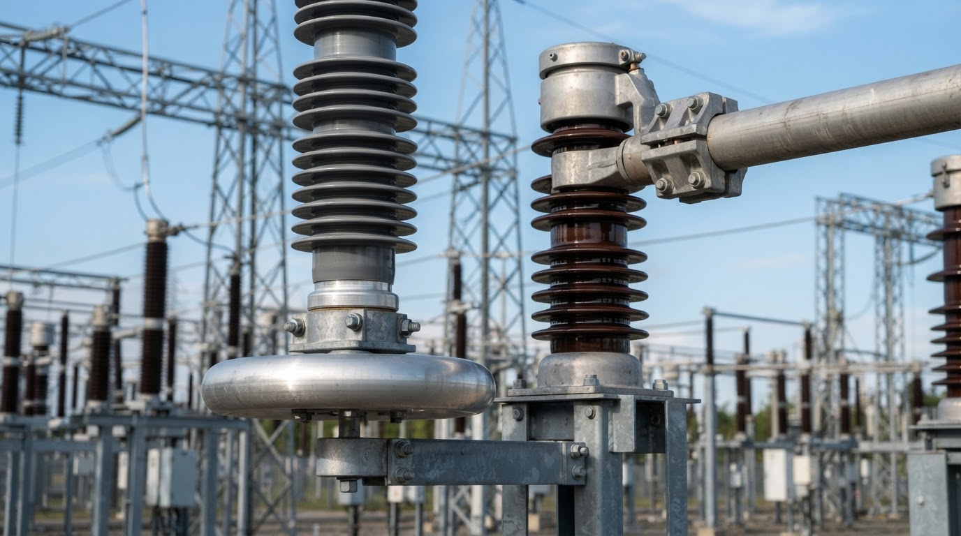
Capacitance to grounded steelwork and adjacent units causes nonuniform AC voltage distribution across suspension discs. The conductor-end units often see greater electrical stress. String efficiency may be expressed as η = Vstring / (n × Vmax-unit) × 100%. Grading/corona rings reshape the field, reducing local stress and risk of discharge-related damage. Their diameter, location and attachment must follow a qualified design.
8. Mechanical and environmental design loads
For suspension strings consider conductor self-weight, hardware weight, transverse wind, ice where applicable, swing angle and broken-wire/unbalanced forces. For tension strings, check longitudinal conductor tension, angle effects, attachments, yoke plates, clevises, pins, sockets and structure interfaces. Parallel strings do not always share load equally. For station posts, check combined cantilever, axial and torsional loading and support flexibility.
9. Tests and factory acceptance
| Test or inspection | Purpose |
|---|---|
| Dimensions and visual examination | Confirm geometry, finish and fittings |
| Mechanical failing-load / proof tests | Validate specified strength |
| Power-frequency wet withstand | External insulation under artificial rain |
| Lightning/switching impulse tests | Transient dielectric withstand |
| Puncture tests | Internal dielectric integrity where applicable |
| Thermal-mechanical tests | Combined environmental/mechanical endurance |
| Tracking/erosion and interface tests | Polymer housing and sealing durability |
| Corona and RIV tests | Local discharge and interference |
| Galvanizing/coating tests | Fitting corrosion protection |
Different tests are design, type, sample or routine tests under their respective standards; they are not all mandatory for every technology or shipment. Require a project-specific inspection and test plan, witnessed tests where specified, and traceable certificates covering the offered configuration.
10. Failure modes and maintenance
Typical defects include pollution flashover, puncture, cracked porcelain, shattered glass, corroded fittings, polymer tracking/erosion, seal failure, composite-core brittle fracture and corona damage. Maintenance should use a risk-based combination of visual inspections, contamination measurements, leakage-current monitoring, ultraviolet corona checks, infrared inspections where appropriate and approved cleaning procedures. Live-line washing requires specialized equipment and formal safety controls.
11. Engineering selection and RFQ datasheet
| Specify in the RFQ | Required detail |
|---|---|
| System data | Nominal voltage, Um, frequency, phase-to-earth/phase-to-phase application |
| Electrical | USCD, nominal creepage, arcing distance, LIWV/SIWV, wet withstand |
| Mechanical | SML/failing load, cantilever/torsion, load combinations, fittings |
| Construction | Material, shed profile, dimensions, end fitting, seal and corrosion protection |
| Site conditions | Pollution assessment, altitude, temperature, wind and seismic conditions |
| Quality | Standards, type tests, sample/routine tests, FAT, ITP and drawings |
| Supply scope | Complete assembly, grading rings, hardware, packing and spares |
12. Relevant IEC standards
Key references include IEC TS 60815 series (pollution-based selection), IEC 60383 series (ceramic/glass line insulators), IEC 61109 (composite suspension/tension insulators), IEC 62217 (polymeric HV insulators), IEC 60168 and IEC 60273 (post insulators), IEC 61952 (composite line posts), IEC 62231 (composite station posts), IEC 60137 (bushings), IEC 60071 (insulation coordination), IEC 60060 (HV test techniques) and IEC 60437 (radio interference). Verify the latest applicable editions and utility project specifications before procurement.
13. Related engineering articles
Continue reading: 380 kV Latticed Steel Structures; Transmission Line Design: Important Points; 380 kV Tower Weight Calculation Template; Circuit Breaker vs Isolator vs Earthing Switch; Transformer Impedance in Substation Design; and Substation Tendering & Contract Management.
14. Engineering learning resources (affiliate)
Affiliate disclosure: Some links below are affiliate links. The World of Engineers may earn a commission from qualifying purchases, at no additional cost to you.
Explore Udemy training and certification offers or additional Udemy learning offers. These tracked links may lead to general certification promotions rather than courses specifically about high-voltage insulators; check the destination and current offer before purchasing. For free Saudi-based professional learning see SCE free engineering courses.
15. Engineering visualizations and design workflow
Pollution flashover progression
Deposits accumulate → moisture wets deposits → leakage current increases → dry bands form → local arcs develop → possible complete flashover. This sequence is conceptual; actual performance depends on contamination chemistry, wetting, geometry and material.
Voltage distribution and string efficiency
For an AC disc string, the conductor-end units can carry a disproportionate share of voltage because of stray capacitance. String efficiency = Vstring / (n × Vmaximum unit) × 100%. The distribution must be verified for the specific geometry, particularly with grading rings.
Mechanical design decision sequence
Conductor and equipment loads → governing load combinations → required mechanical capacity → complete hardware verification → supplier drawings and type-test review → approval.
16. Final engineering conclusion
Correct insulator selection requires coordinated electrical, pollution, mechanical and environmental verification. Creepage distance alone cannot demonstrate impulse withstand, and a high kN rating alone cannot establish safe working loads. Final approval must cover the entire insulator and hardware assembly, site-specific pollution assessment, test evidence and the utility’s approved technical specification.