A current transformer can become hazardous when its secondary circuit opens while primary current continues to flow. A Current Transformer Protection Unit, or CTPU, provides a permanent secondary-side protective path. For substation engineers, the practical challenge is to select the right device, protect the correct cores, place it correctly and account for every enclosure and alarm.
This guide explains conventional inductive CT applications in 132 kV and 380 kV AIS and GIS. It includes original diagrams, calculation examples and a tendering checklist. Numerical examples and cabinet arrangements are illustrative unless identified as manufacturer data.
1. What a CTPU actually protects
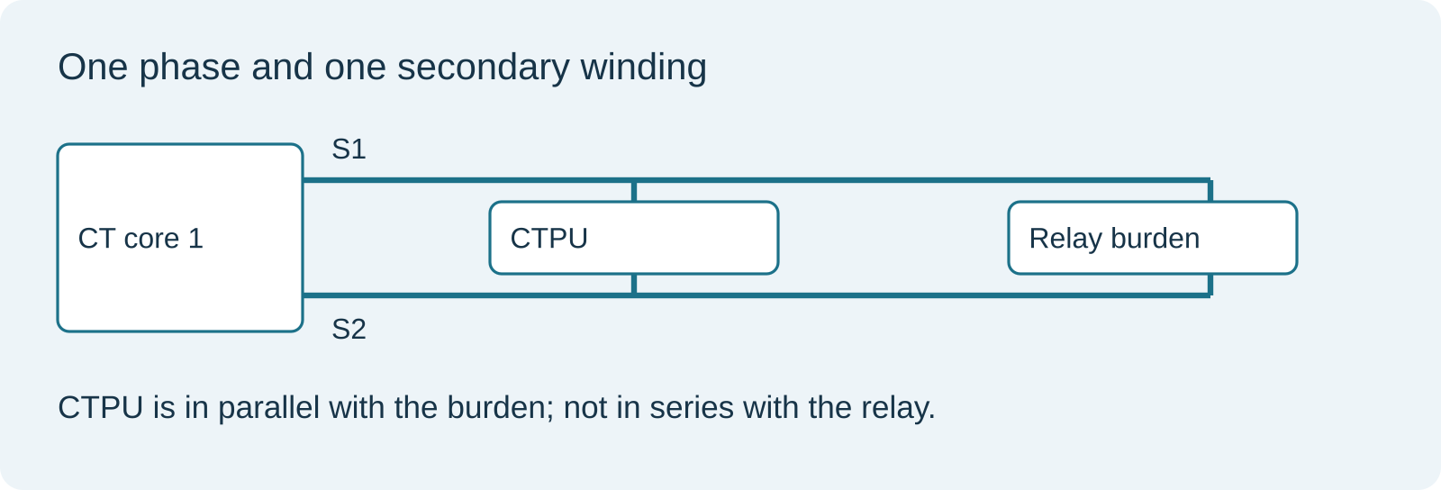
A CT supplies scaled current to protection relays and meters. If a secondary lead breaks or a burden is disconnected, the open winding can develop high voltage. A CTPU limits that voltage across the winding it protects. Metrosil is a manufacturer and trade name associated with silicon-carbide nonlinear resistors; the term is often used loosely in BOQs for either a component or a complete protection assembly. These are not automatically equivalent. [1]
| Term | Meaning in a technical review |
|---|---|
| CT core | A magnetic core and its associated secondary winding, designated for a particular protection or metering duty. |
| Single-pole CTPU | One protective channel for one secondary winding in one phase. |
| Three-pole assembly | Three protection channels packaged together. Commercial item count may be one assembly. |
| CTPU cabinet | An enclosure housing channels, terminals, wiring and any specified monitoring equipment. |
| CT junction box without CTPUs | A secondary connection enclosure. Its name or connection capacity does not establish that protective devices are installed. |
In quantity schedules, describe both the number of channels and the number of purchased assemblies. Otherwise, “18 CTPUs” could be misunderstood as 18 single-pole devices or 18 three-pole assemblies.
2. Why an open CT secondary develops voltage
Under ordinary operation, primary and secondary ampere-turns approximately balance, with a smaller magnetising component. In simplified notation:
NₚIₚ ≈ NₛIₛ + magnetising ampere-turns
Opening the external secondary circuit removes its normal current path. Core flux becomes highly nonlinear, and the resulting secondary voltage may contain sharp peaks. Neither the CT ratio nor its knee-point voltage gives a direct numerical prediction of the open-circuit waveform.
Faraday’s law describes the underlying connection:
eₛ(t) = Nₛ × dΦ(t)/dt
The winding voltage follows the rate of change of magnetic flux. A saturated waveform must not be treated as a simple sinusoid. Schneider Electric specifically warns against operating a CT with an open secondary while primary current can flow and identifies shorting blocks as part of installation and servicing practice. A CTPU is additional protection; it does not authorise opening a live CT circuit. [4]
3. How a Metrosil CTPU works
The published Metrosil design combines a varistor disc with a parallel thermostatic switch on a heat sink. With the burden connected, the device draws low leakage current. During an open circuit, the varistor provides a voltage-limiting current path. The thermostatic mechanism manages thermal cycling; an additional thermostatic switch can provide remote monitoring. These details describe this product family, rather than every device marketed as a CTPU. [1]
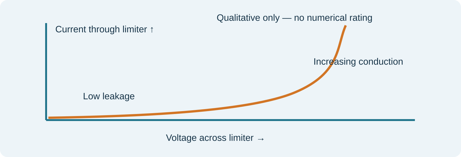
A voltage limiter is not an ideal switch with one universal turn-on voltage. Its voltage-current characteristic, leakage, temperature behaviour and duty capability must be considered together. The voltage during a hazardous event is therefore a result of the device characteristic and applied current, rather than simply a value printed as the CT knee point.
4. CTPU versus Metrosil for high impedance protection
| Aspect | CT open-circuit CTPU | High-impedance relay Metrosil |
|---|---|---|
| Design event | Open secondary circuit | High voltage during an internal fault in a high-impedance scheme |
| Application | Across the protected CT secondary winding | Across the appropriate scheme branch as the relay manufacturer specifies |
| Review focus | Open-circuit limiting, leakage and thermal behaviour | Setting-voltage coordination, fault current and energy duty |
| Interchangeable? | No. Common nonlinear-resistor technology does not establish equivalent duty. | |
High-impedance busbar or restricted-earth-fault schemes need stability during external faults while remaining sensitive to internal faults. A scheme voltage limiter must coordinate with the relay setting and stabilising arrangement. Metrosil identifies relay setting voltage and maximum secondary internal-fault current as relevant selection parameters. [3]
Do not assume that adding an open-circuit CTPU to a high-impedance scheme is electrically harmless. Any added shunt path can affect the operating circuit. Obtain coordinated approval from the CT, CTPU and protection-system designers when both functions are present.
5. Understanding knee point voltage and project thresholds
Knee-point voltage, Vk, characterises the excitation behaviour of a CT core. For the IEC-style definition described in OMICRON’s CPC 100 documentation, a 10% increase in applied excitation voltage produces a 50% increase in excitation current. The applicable test method and CT specification must be stated. Vk is not the primary system voltage, an insulation withstand rating or a guaranteed maximum open-circuit voltage. [5]
Consider a project requirement that makes CTPU protection mandatory for CTs having Vk ≥ 2,000 V, subject to engineering approval:
| Core Vk | Result under that threshold alone |
|---|---|
| 1,400 V | Below the threshold; the clause does not trigger protection. |
| 2,000 V | Included, because the comparison is “greater than or equal to”. |
| 2,500 V | Above the threshold; protection is required subject to approval. |
This is an interpretation of an example project clause, not a universal IEC requirement. Another specification may require protection at a different threshold or for all designated cores. Being below a contractual threshold does not mean an open secondary is safe.
Distinguish a guaranteed minimum such as “Vk ≥ 1,400 V” from an actual or guaranteed upper value. It does not prove that the manufactured core will remain below 2,000 V. If the threshold affects scope, resolve whether applicability is assessed against the specified requirement, approved design value or measured test value. Record that decision before final quantities are agreed.
6. Application in 132 kV and 380 kV AIS and GIS
| Installation | Typical physical interface | Design question |
|---|---|---|
| 132 kV AIS | Outdoor CT secondary terminal boxes and marshalling cabinet | Where can the device remain connected during relay-side maintenance? |
| 380 kV AIS | Multiple secondary cores from outdoor CTs | Which cores qualify and how many independent CT positions exist? |
| 132 kV GIS | GIS CT secondary terminals and vendor cabinets | Is protection included in the GIS vendor’s approved secondary design? |
| 380 kV GIS | Integrated CT locations with multiple protection circuits | How do CT positions, core duties and protection zones map to cabinets? |
These are typical engineering interfaces, not a statement that every installation requires CTPUs. AIS or GIS classification does not alone establish applicability. Nor should a 380 kV device automatically be selected as a larger secondary limiter than one serving 132 kV equipment. Primary insulation duty belongs to the CT and switchgear; secondary protective duty must be evaluated from the secondary circuit.
In breaker-and-a-half arrangements, count the actual CT sets at the relevant breaker positions. A feeder count can differ from the CT-set count. Likewise, future bays should only contribute installed devices if their CTs and protection channels are included in the present supply scope. GIS supply responsibility must follow the purchase specification and agreed scope split, rather than an assumed industry custom.
7. How to count CTPUs from CTs and cores
Start with an inventory of secondary windings. For a uniform arrangement:
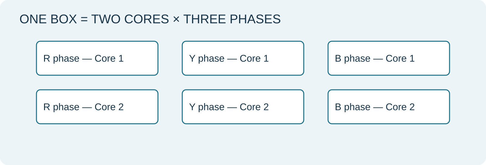
Single-pole channels = three-phase CT sets × 3 × protected cores per phase
If the source schedule already counts individual single-phase CTs, do not multiply by three again:
Single-pole channels = individual single-phase CTs × protected cores per CT
For mixed duties, sum each CT position and each qualifying phase-core winding individually. Do not multiply the total installed core count when only some cores qualify.
| Illustrative arrangement | Calculation | Channels |
|---|---|---|
| One three-phase set, two protected cores per phase | 1 × 3 × 2 | 6 |
| Five sets, two protected cores per phase | 5 × 3 × 2 | 30 |
| Seven sets, six protected cores per phase | 7 × 3 × 6 | 126 |
| One set with six installed cores but only two qualifying cores per phase | 1 × 3 × 2 | 6, not 18 |
The 126-channel example is only one possible configuration. It cannot establish what a particular 126-unit cabinet actually contains.
Boxes require a separate calculation
One six-channel cabinet per CT set with two protected cores gives one box per set. Dividing total channels by six only works when combining circuits is permitted and each location can use that cabinet arrangement. A cabinet serving a separate bay may still be required even when space remains in another cabinet.
| Example BOQ group | Boxes | Channels per box | Total channels |
|---|---|---|---|
| Group A | 5 | 6 | 30 |
| Group B | 5 | 6 | 30 |
| Group C | 8 | 6 | 48 |
| Connection boxes without CTPUs | 2 | 0 | 0 |
| Additional connection boxes without CTPUs | 2 | 0 | 0 |
| Group D | 1 | 6 | 6 |
| Total | 23 | — | 114 |
This example shows why total boxes, protected windings and CT connection capacity must remain separate quantities.
8. Selecting a device from electrical duty
The manufacturer’s published selection method distinguishes metering and protection applications, then checks secondary current, burden and protection fault-current multiple. It also requires verification of leakage under normal and fault conditions, permissible limiting voltage and monitoring provision. Use the current data for the offered model; a cabinet dimension is not an electrical rating. [1]
The following calculations are engineering screening examples, not a complete CTPU selection:
|Z| = burden VA / Iₛ² and |Vterminal| ≈ |Iₛ Zexternal|
A 1 A circuit with 15 VA external burden corresponds to 15 Ω and about 15 V at rated current. A 5 A circuit with the same 15 VA burden corresponds to 0.6 Ω and about 3 V. State whether the quoted burden is actual external burden or merely the CT’s rated burden. Include cable and terminal contributions where appropriate.
For an illustrative 2,000/1 A CT at 40 kA primary fault current, the ideal ratio-derived secondary current is 20 A. With 15 Ω external burden, the simple resistive estimate is 300 V rms. This is a screening value: saturation, excitation current, transient DC offset and the actual impedance alter the result. The internal induced emf also includes the winding voltage drop. These calculations do not predict open-circuit peak voltage.
Review that the limiter does not materially divert the current needed by the relay or meter during legitimate duty. Also confirm its limiting characteristic against the withstand of all affected secondary components. Never compare a peak limiting value directly with an rms withstand or knee-point value without establishing the measurement basis.
9. Alarm grouping and SAS integration
A requirement for one common three-phase indication per core usually means that operation of any phase’s monitoring contact produces that core’s common alarm. It does not mean one common alarm for every core in the bay.
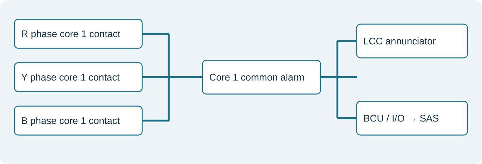
For five three-phase CT sets with two protected cores per phase, there are 30 single-pole channels and normally 10 common core alarms under this grouping rule. The count of physical I/O points depends on architecture. Hardware grouping before the BCU can use one input per common alarm; individual phase inputs with software grouping need three inputs per core group. Local annunciator and SAS paths may need separate contacts or interposing relays.
Distinguish the detected event. A thermostatic contact reports a temperature-related state; it is not automatically an instantaneous voltage detector. If the project explicitly calls for overvoltage detection, obtain approval for the proposed sensing mechanism, response time, alarm text and reset behaviour. Define behaviour after a brief event and during auxiliary-supply loss.
A useful signal name identifies bay and core: “Bay 05 CT Core 2 CTPU Operated”. Specify whether the signal is latched, acknowledged locally, time-stamped and separately reset. Do not add automatic tripping solely because an alarm exists; tripping requires its own approved protection philosophy.
10. Cabinet design and installation details
Metrosil publishes pre-assembled enclosures with different channel capacities, mounting arrangements and signal configurations. The referenced range includes IP66 enclosures and declared IEC 61439 Parts 1 and 2 certification. This does not certify a separately fabricated custom cabinet containing the same components. [2]
For a custom assembly, check thermal dissipation for the agreed simultaneous operating duty, ambient temperature and solar exposure. Also review channel spacing, protection barriers, cable bending space, gland entries, corrosion resistance, labels and terminal access. A 1,200 × 800 × 300 mm enclosure cannot be accepted as adequate for 126 channels from dimensions alone.
Locate the protection so that an opening in the circuit to be protected does not also remove the CTPU from the winding. The manufacturer recommends installation close to the CT. [1] Maintain approved shorting arrangements and secondary earthing. Do not create extra earth points when adding the cabinet, and do not casually bridge different cores or ratio taps.
11. FAT and commissioning checks
Develop an approved inspection and test plan with the supplier. The following are proposed acceptance checks, not a substitute for the product test procedure:
- Reconcile every installed channel to the CT core schedule, winding terminals and device model.
- Verify wiring continuity, polarity identifiers, tightening records and the intended connection across each winding.
- Confirm that relay-side test isolation preserves the designed CT shorting and protective paths.
- Demonstrate each monitoring channel using the manufacturer-approved test method.
- Verify three-phase grouping separately for every core, then check annunciator, BCU or I/O and SAS indications.
- Confirm alarm acknowledgement, reset, supply-failure behaviour and event time stamps where specified.
- Review product test certificates, cabinet verification, terminal drawings and final as-built records.
Do not deliberately open an energised CT secondary to prove operation. Nonlinear devices can affect excitation measurements and insulation testing; follow the approved isolation and reconnection procedure for the particular test. Restore and independently verify all protective connections before service.
12. Tendering and procurement checklist
| Document or input | What to confirm |
|---|---|
| CT schedule | Set versus individual CT quantity; ratios; phase; core IDs; class; Vk; burden; winding resistance where needed. |
| Applicability matrix | Which cores qualify, the governing clause and the agreed basis of the Vk threshold. |
| Device schedule | Channels, assemblies, electrical model, monitoring contacts and spare requirements. |
| Cabinet schedule | Location, channel capacity, thermal duty, enclosure specification and mounting. |
| Alarm schedule | Phase grouping, core identification, contact/interface quantities and I/O allocation. |
| Scope split | Who supplies devices, cabinets, cables, annunciator changes, I/O, SAS configuration and testing. |
| Approval package | Selection justification, coordinated schematics, cabinet drawings and supporting certificates. |
Price the complete working interface. A low device-only price can omit cabinet assembly, monitoring contacts, field cables, spare terminals, SAS engineering and end-to-end testing. Conversely, do not duplicate CTPUs already included in an OEM’s approved package. Contractual responsibility and any variation entitlement require the actual contract documents.
13. Frequently asked questions
Does every CT core need a CTPU?
Determine this from the project specification and approved design. Do not assume either universal inclusion or universal exemption based on voltage level.
Does Vk equal 1,400 V trigger a clause requiring Vk ≥ 2,000 V?
No, if 1,400 V is the applicable established value. A minimum specification written as Vk ≥ 1,400 V needs further clarification because it does not set an upper limit.
Does a six-core CT mean six devices for a three-phase bay?
If each phase has six protected cores, it means 18 single-pole channels. If only two cores per phase qualify, it means six channels.
Can one box serve multiple bays?
Only where the approved layout, wiring, maintainability and thermal design allow it. Arithmetic capacity alone does not determine the cabinet arrangement.
Does an alarm prove direct voltage measurement?
No. Establish whether the contact represents voltage, thermal operation or another device state, and obtain approval for its intended use.
Is a CTPU a substitute for CT shorting terminals?
No. Retain the prescribed safe isolation and shorting arrangements.
References
Primary manufacturer sources checked 10 November 2026. The 2,000 V threshold, BOQ quantities, proposed review checks and calculation examples are project interpretations or original explanatory examples, not manufacturer mandates.
- Metrosil Current Transformer Protection Units — data sheet, January 2024.
- Metrosil CTPU Enclosures — manufacturer brochure.
- Metrosil — Relay protection and high-impedance applications.
- Schneider Electric — CT shorting blocks and open-secondary hazards.
- OMICRON CPC 100 User Manual — CT excitation and knee-point definition. The search-indexed manual excerpt was available; direct download access was restricted during this review.